Let us try to understand simulation of a typical Orthogonal Frequency Division Multiplexing (OFDM) transmission defined per IEEE 802.11a specification.
Orthogonal pulses
In a previous post (here ), we have understood that the minimum frequency separation for two sinusoidals with arbitrary phases to be orthogonal is , where
is the symbol period.
In Orthogonal Frequency Division Multiplexing, multiple sinusoidals with frequency separation is used. The sinusoidals used in OFDM can be defined as (Refer Sec6.4.2 in [DIG-COMM-BARRY-LEE-MESSERSCHMITT]:
, where
correspond to the frequency of the sinusoidal and
is a rectangular window over
.
Using of inverse Fourier Transform
We now have understood that OFDM uses multiple sinusoidals having frequency separation where each sinusoidal gets modulated by independent information. The information
is multiplied by the corresponding carrier
and the sum of such modulated sinusoidals form the transmit signals. Mathematically, the transmit signal is,
The interpretation of the above equation is as follows:
(a) Each information signal multiplies the sinusoidal having frequency of
.
(b) Sum of all such modulated sinusoidals are added and the resultant signal is sent out as .
Update: 29th May 2008
(thanks to the comment by Mr. Mork)
The sampled version of the above equation is,
It is reasonable to understand that above operation corresponds to an inverse Discrete Fourier Transform (IDFT) operation.
Understanding of an OFDM transmission specified per IEEE 802.11a [80211A]
From the Table 79 in [80211A], the symbol duration .
This implies that the used subcarriers are and so on.
The available bandwidth of 20MHz is split into 64 subcarriers. Out of the available 64 subcarriers having indices , the number of used subcarriers is 52. The used subcarriers are having indices from
are used for transmitting information sequence
to
.
To understand in detail the correspondence between the subcarrier index and frequency, one may refer to a previous post (here).
Once the bits in each symbol are assigned to appropriate IDFT inputs (Ref. Figure 109 in [80211A]), the IDFT operation is performed to obtained the time domain signal.
For each symbol, some samples from the end are appended to the beginning of the symbol (referred to as cyclic prefix insertion). We may discuss the pros/cons of cyclic prefix in a future post.
Simulation Model
A simple Octave script where a BPSK modulated signal is transmitted on the 52 used subcarriers, may be used for understanding generation of an OFDM signal. The script is loosely based on 802.11a specification.
Click here to download.
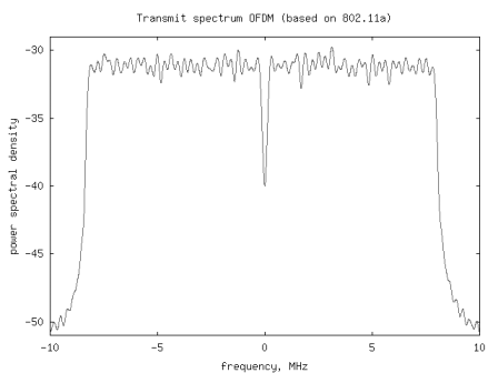
Figure: Spectrum of an OFDM transmission (based on 802.11a specification)
Reference
[DIG-COMM-BARRY-LEE-MESSERSCHMITT] Digital Communication: Third Edition, by John R. Barry, Edward A. Lee, David G. Messerschmitt
Hope this helps.
Krishna
Hi sir,
Why we are using only 52 out of 64?
@shamseer: The subcarriers on the edges are kept unused to allow for a reasonable transition band at channel boundaries. Further, the subcarrier at dc is also not used.
Dear Krishnan anna,
In OFDM multicarrier modulation why we are modulating with sine and cosine signal why can’t we modulate with either sine or cosine signal only
with regards
Arunpradhap Natarajan
@Arunpradhap Natarajan: We are sending information on complex sinusoidal which has only one sided frequency component.
https://dsplog.com/2008/08/08/negative-frequency/
hi sir,
i’m doing project in wireless communication….our project tittle is mitigation of impulsive interference in ofdm system…in our base paper NEYMAN PEARSON testing is used to detect interference….any other advanced testing is available to mitigate te interference….ana also expln tis qstn
Plz explain GLRT?
why we adding pilot in ofdm tx?
wat is cyclic prefix?
@Preetha:
– sorry, do not know GLRT
– pilots are added to help the receiver track the residual phase/frequency errors
– cyclic prefix is added as a buffer between two symbols to prevent inter symbol inteference
https://dsplog.com/2008/02/17/cylcic-prefix-in-orthogonal-frequency-division-multiplexing/
Hi krishna,
Few doubts
a) How is the nBitPerSymbol = 52 is decided ?
b) In the code you are using BPSK modulation, so each subcarrier carries 1-bit information, is this understanding correct ?
c) if we are using QPSK , each subcarrier carries 4-bits of information, am I right ?
d) does 802.11a specifies which modulation to be used ?
Could you please answer these if possible
regards
bijoy
@bijoy: Replies/
a/ The number 52 is decided by the specification. For 802.11a/g the number of used subcarriers was 52, when 802.11n came it was slightly increased to 56 and so on…
b/ Yes, for BPSK, each subcarrier carries one bit of information.
c/ For QPSK each subcarrier carries 2 bits of information.
d/ Yes. The modulation and coding rate is defined in the specification. Starting from BPSK, rate 1/2 (for 6Mbps), it goes all the way to 64QAM rate 3/4 (for 54Mbps).
Hi, I read your article and I have a doubt. You have given the set of subcarriers when we implement IFFT in TX and FFT in RX… Will this set of subcarriers change if we implement FFT in TX and IFFT in RX?
@akshaya: swapping to fft in tx and ifft in rx does not change the subcarrier frequency – however it does affect the bin where the modulation information goes. for eg, the information which was going on subcarrier bin +10 will go to -10 and so on…
dear sir,
If DPSK is used other than PSK what is the advantage in terms of reference carriers (preamble) ?
@achuse: Well, since we are interested in having only a known sequence in the transmitter – am not sure that DPSK will bring in advantages over PSK. What do you think?
sir,
if DPSK is used, then the receiver do not need the reference to decode the data since the phase is compared with the previous symbol which is just before the current symbol. so if some phase change had occured and it is evenly affecting all the symbols, then we do not want to cancel the effect since we are taking the difference between the pahses to identify the data ? that means no need of correction?
@achuse: Hmm.. but for preamble, the case for DPSK does not exist, right?
dear sir,
suppose I have 104 datas are to be sent in 52 subcarriers by BPSK. when iam plotting the frequency response after IDFT(before adding cyclic prefix) i can see positive and negative peaked subcarriers for 1 and -1 respectively. ie at the position of each carrier there will be EITHER negative or positive peak and it can be seen clearly. but how did it happen? ie when i send the second symbol (ie next 52 datas) which are different from the first symbol, is the amplitude at each frequency should be the mix of the both (first 52 data and second 52 data)?
@achuse: When you find the frequency response, you are practically undoing the effect of IDFT and getting back the source I/Q symbols which you used.
Thank you sir,
ie ok sir, so what we obtain is the 2nd set of 52 datas? it has nothing to do with first set of 52 datas?
@achuse: each ofdm symbol is typically independent and does not have any relation with the previous symbol.
sir,
Why does the carriers in the middle range DFT points not used? In other specifications also only few DFT points are used. what may be the reason? can it be linked with frequency offset or windowing? can you please explain how timing offset can be synchronized? also can you explain why PSD decreases with increasing sampling frequency?
@achuse: My replies:
1. The middle range DFT points corresponds to the edges in the frequency band. Typically, those subcarriers are left unused to allow for slow rolloff of the filter transition band.
https://dsplog.com/2008/08/08/negative-frequency/
2. Pilots present in each symbol is used to synchronize for timing offset. Typically, timing offset results in a linear phase growth in frequency domain, and this linear phase is used to synchronize. WHen the timing growth exceeds more than a sample duration, then a sample skip/repeat need to be used.
3. I think that is a notional concept – PSD is represented in dBm/Hz (or /MHz etc). When the sampling frequency changes, the resolution of each subcarrier is fs/nfft, and the PSD is scaled accordingly.
Hope this helps.
i would like to get a matlab code for a 1 transmitter and n number of recievers, where the transmitter is transmitting a qpsk ofdm signal with 64ifft and the n receivers should receive it with 64 fft.. the SNRs are 10 db and -5db in two cases.. it is also said that that qpsk ofdm signal is transmitted in between a band of 0.25 to 0.75 (normalized frequency)
@Rahim: Please check out
https://dsplog.com/2008/06/10/ofdm-bpsk-bit-error/
Hi,
In OFDM, why the center subcarrier (subcarrier 0) is inactive?? Can you please shed some light on this?
Thanks in Advance!
@chithra: The 0’s the subcarrier tries to send information on the DC signal. Typical transmitters and receivers will have additional leakage on the dc level OR ac coupling thereby increasing the chances of error in the demodulation. Hence dc is not used.
I have been trying to simulate ofdm with double differential modulation to avoid the effects of carrier frequency offsets.I used function ifft directly for finding IFFT.could you please tell me how to introduce a carrier frequency offset.I tried it by multiplying the transmitted signal with exp(1i*2*pi*frequency offset*t),but it was not working
@abhisha: multiply with exp(j*2*pi*fd*t), where fd is the carrier frequency offset and t is the sampling time.
The post on carrier frequency offset with ofdm has an example :
https://dsplog.com/2008/03/03/frequency-offset-estimation-using-80211a-short-preamble/
Hi,
Please suggest me recent research topic in ofdm.
Do you have information about OFDM papr reduction by Shifting Null Subcarriers?
@swapnil: I have not tried modeling the papr reduction by playing with null subcarriers
Hi,
Suppose I want to suppress some of the sub-carriers, the intuitive way is to multiply it with 0 or use some notch filter. I tried the code which you have given but couldn’t find some way to multiply the corresponding subcarrier argument with zero. Can you throw some light about where I need to modify in the code.
Sumit
@Sumit: The columns of the variable ipMod corresponds to subcarriers. You can try making all the elements of one of the column zero.
Thanks.. it worked 🙂
I would like to clarify with the fact that, when we talk of ofdm does the orthogonality simply means the carriers are orthogonal? if so then how will it differ from a simple fdm at the implementation level of any receiver?
@pallavi: The key is that carriers which are very close to each other are still orthogonal. A classical FDM uses frequency separation to achieve near orthogonality.
Hello Krishna,
Can you please also explain something for WCDMA signals?
How to generate them in matlab
Regards
@Shoaid: Will do
Hi Krisna,
From the reading I understand that out of 64 sub-carrier, 52 is used for data transmission. But from the code
ipMod = [ipMod zeros(1,nBitPerSymbol*nSymbol-nBit)];
ipMod = reshape(ipMod,nSymbol,nBitPerSymbol);
since you inserted zeros, each row of ipMod have less than 52 bpsk symbols (-1 & 1) except the first row. Is this OK ?
Please help me.
@Hasan: Each row of the variable ipMod has 52 subcarriers having +/-1 values. Then 12 zeros are inserted to make it a 64 element vector.
Hi K. Sankar,
I saw all your post. very nice all of them. my question is this “can you specified for applicability of all your post in game-theoretic aspect”, please try to explain one post regarding power allocation in physical layer using game-theory.
Thanks
Regads
Arun
@Arun: Hmm… game theory…i ‘ve not really thought about this topic. will add this as one of the to do’s
sir help me out in my thesis please guide me to develop my thesis my dates are near i am working on OFDM system PAPR reduction using Amplitude clipping my base paper is
Clipping Based PAPR Reduction Method for LTE
OFDMA Systems by M.M. Rana published in Ijecs it is also available in google also,Please sir help me
@eshan: good luck
Hi Krishna,
I want to know that whether ak is in frequency domain. if so do we convert them in to frequency domain before feeding into IFFT.
@harsha: yes, ak is in frequency domain
Hi Krishna,
So how do we make sure that ak is in frequency domain. Do we apply any type transformation techniques before feeding in to OFDM modulator and after modulating the bits (either by QAM or QPSK).
@harsha: consider that ak’s are going to change the amplitude (and phase of) sinusoidal waves.
what is the use of upconverter in the transmission of OFDM
@satya: to convert the basedband signals to passband
Hi Krishna,
Thanks very much for your matlab codes. They are really useful for wireless researches.
I am implementing a carrier recovery system and symbol recovery system for a wireless system which uses frequency domain equalization. I tried to find some matlab codes on carrier recovery, but no matlab codes are available.
Could please help me to find a m file code on carrier recovery?
Thanks in advance.
@Dinu: The carrier recovery in OFDM with periodic preamble sequence is discussed in
https://dsplog.com/2008/03/03/frequency-offset-estimation-using-80211a-short-preamble/
@krishna
Your codes are really useful Thanks for your helping.
Have you done any work IDMA-OFDMA ? If yes, can you send me the codes.
Thank you.
@Burhan: Sorry nothing yet posted on IDMA-OFDMA
@krishna Do you have matlab code for OFDM transmitter and receiver using frequency selective fading channel.
@Deepraj: Please take a look at
https://dsplog.com/2008/08/26/ofdm-rayleigh-channel-ber-bpsk/
@krishna
i need help to do ofdm simualtion for lte system downlink shared channel
can you write an article a bout that
it’s very important for me
@saeed: I have not spend time on the LTE spec. Will do so…
thanks
but it’s somehow i cant understand specs to be simulated
and have a lot of questions but I’m working and did my effort
really your blog is very very important and very useful keep going
appreciate your hard work
thank you
IN th abovce spectra 0 to 10 Mhz will cover all 52 subcarrier?
if am doing somthing like
ipMod (:,1:10)=0;
(after BPSK mod and reshape ),band is getting removed from negative frequecy portion only..
why it so?
@rajsh: Hmm… if the sampling frequency is 20MHz and the fftsize is 64, then the fft indices from [-32 to 31] correspond to [-10MHz to 10MHz).
Hi Krishna,
i have a question about the pwelch() function ,in ur code,like this:
*************************************************************
fsMHz = 20;
[Pxx,W] = pwelch(st,[],[],4096,20);
plot([-2048:2047]*fsMHz/4096,10*log10(fftshift(Pxx)));
xlabel(‘frequency, MHz’)
ylabel(‘power spectral density’)
title(‘Transmit spectrum OFDM (based on 802.11a)’);
************************************************************
the fifth parameter ’20’,i know it is the rate of sampling.But,our rate is 20 000 000,not that 20.
so ,is there something i ignore or some logical in that expression,why do you put ’20 ‘ in that place instead of 20000000?
@Michael: Well, the sampling frequency is a notional in matlab. So, if its 20Hz it means we can ‘see’ frequencies from [-10Hz to +10Hz); and if it is 20MHz the range is from [-10MHz to +10MHz).
Helps?
Hello,
Changing 20MHz to 20Hz will change the level of the PSD estimate given by pwelch() function. For 20Hz you have a PSD around -30dB but with 20MHz you have a PSD of -90dB. And it comes from the scaling by f_sampling in pwelch(). You can check it by changing the sampling frequency.
cordially
@Invizible soul: Yes, thanks.
Hi Krishna,
Any thoughts on reason for the OFDM spectrum not to be rectangular? I am simulating real, unipolar ofdm signal, but the psd estimate gives me half of raised-cosine filter like shape. I am intrigued. Please can you email me back if you do reply. Many Thanks.
@Jo: Well, unless you are doing some filtering, it should be close to rectangular…
@Krishna: can you send me a copy of probability of error book. thanks
@MFS: emailed you the instructions
@Krishna: thanks, received
Hi Krishna
I am doing a project on Dynamic Bandwidth allocation in OFDMA transmission.Do you have any MATLAB codes for fundamental bandwidth allocation for GPON or in OFDMA, as I am new to the matlab any information or codes on this area will be helpful to me. Thanks a lot….
@Toms: Sorry, I do not have any code handy
its really a good article.thanks..
Hi Krishna,
do you have a matlab code regarding how to create an orthogonal pulse like Hermite pulse and the demodulation of this these pulses?
regards
@MFS: What is Hermite pulse?
@Krishna: Hermite pulse is an orthogonal pulses created from a modification of the Hermite polynomials (http://en.wikipedia.org/wiki/Hermite_polynomials) and it is used in digital communication in a fashion like OFDM.
@MFS: Thanks. I have quite a bit to learn out there.
Can you also point me to the UWB specification which uses this concept?
@Krishna: you can find in this paper one way of using this pulses with UWB (http://www.cwc.oulu.fi/~giuseppe/index_files/MyPapers/On%20the%20Design%20of%20Orthogonal%20Pulse-Shape%20Modulation%20for%20UWB%20Systems%20Using%20Hermite%20Pulses.pdf)
@MFS: Thanks, will study that.
hi krishna
i am new to matlab. can you send me basic script for transmitter and receiver using 64 qam modulation with addition and removal of cyclic prefix
@Nanu Nadoda: You may find code for 64QAM @
https://dsplog.com/2008/07/08/compare-bpsk-qpsk-4pam-16qam-16psk-64qam-32psk/
hi krisna,
Could you do an article about understanding the MC-CDMA too? I know it is a little bit similar to OFDM and I have also read some paper on MC-CDMA. I just dont really get how to implement the coding (which is in frequency domain) and the message bit in Matlab. Do I need to multiply them together in the frequency domain or ifft the coding first and then multiply with message bit?
Thanks
@Afm: Have not written about MC-CDMA, will write in future…
Hi krishna
In OFDM system is a mapping blocks, data blocks will be put back into the IFFT, so the question is which blocks any effect?
thank you!
@thieutuoc: Sorry, I do not follow your query.
Sorry Krishna, I mistake. It is digital modulation block (QAM).
Thanks Krishna!
hi krishna,
OFDM system has a block of data Mapping is then brought through the block ifft data, so I want to know what to do for mass Mapping.
thanks!
@thieutuoc: What is mass mapping? Are you referring to QAM mapping?
hi krishna
i want to know how to define separation frequency between the sub-carrier in ofdm.
it the way i have found with ifft command this frequency is 1 Hz.
thanks krishna
@behzad: Well, subcarrier spacing is controlled by the sampling clock and the number of points in the FFT. For examples, if the sampling clock is 20MHz and the FFT size is 64, the subcarrier spacing is 20MHz/64 = 312.5kHz
Can I understand the sampling clock is the sampling rate of DAC? For example, at 20MSa/s sampling rate, symbol period T=64*1/20(MSa/s)=3.2 (microsecond). Therefore, the subcarrier spacing is 1/T=312.5 kHz.
@dungpt: Your numbers are right. You can assume that the sampling period is the sampling period of the FFT. Sampling period of DAC need not be sampling period of iFFT. Typically, DAC can have 2x/3x oversampling compared to fft sampling rate.
i want to ask that what if i sample with a sampling rate of 15Mhz
and if i sample with a rate of 40 Mhz will there be any negative frequency components present in the signal .
secondly does the concept of complex discrete fourier transform has anything to do with the negative frequencies
or the concept that the transform magnitude of the real signal is composed of signal at the negative frequencies and the positive frequencies, has anything related to this notion
@tikio:
1) The 15MHz ‘real’ signal has both +ve and -ve frequencies.
recall : cos(wt) = ( e^(jwt) + e^(-jwt) )/2
2) fourier transform uses e^(jwt) as basis functions
Hello Sir,
Thanks a lot for the reply,
Could u please guide me as to how a receiver is designed,I am not able to recover the samples.I am using 64QAM and I am mapping the data and dividing it into subblocks,as the definition of OFDM goes..
after the ifft,i tried to to do the fft but the samples are not getting recoverd,they get scaled..
please help me for the same.
@vedika: If the scaling factor is constant across all subcarriers, then it can be easily accounted for. Agree?
Hi Krishna,
I had to include a Simulink model for clarification. So I’ve sent my doubt to your mail. Kindly check it out.
@Chaitanya: Answering in the comments will be faster than emails (am running a bit late on blog related email queries)
I will wait for your reply to the mail. Meanwhile, can you explain the need for training insertion and zero padding in OFDM? Also, the function of channel estimation and compensation in the receiver.
These were few of the blocks i encountered in the model.
Also, in he OFDM transmitter, the blocks were in this order
Bit generator —- RS encoder—- QPSK modulator —- Row Selector —- Matrix concatenation(first Vertical, then Horizontal) —- zero pad —- IFFT —- Cyclic prefix —- Training Insertion —- Parallel to Serial converter.
The vertical matrix concatenation block had 3 inputs(two from the row selector and the other is constant zero)
The horizontal matrix concatenation block had 2 inputs(one from the preceding vertical block and the other from a block denoted TR)
The TR block consisted of:
PN seq generator —– Unipolar to bipolar conv
The training insertion block consisted of:
Column selector —– Horizontal matrix concatenation
All this was there in the Simulink model i attached to your mail. So if u could give me the purpose of the various blocks when your time permits, it would be invaluable.
@Chaitanya:
a) In frequency domain, we do not want to use subcarriers at the edge (and also at DC). Hence these subcarriers are nulled out.
b) In typical OFDM systems, the system model can be written as
Y = HX + N, where
Y – is the received symbol
H – is the channel
X – is the transmitted symbol
N – is the noise.
To accurately demodulate X, we need to undo the effect of channel prior to demodulation.
So Yhat = Y/H = X + N/H ~= X (if N is low) —> this is channel compensation
For estimating channel, we will send a symbol where X is known at the receiver.
Hhat = Y/X = H + N/X ~= H (if N is low) –> this is channel estimation
Thanks for the explanation. The nulling out of subcarriers explains the zero padding block. But what about the training pulses inserted in the transmitter and separated at the receiver?
@Chaitanya: The training sequence help the receiver synchronize with the transmitter – to help with channel estimation, phase synchronization etc
hello krishna
I simulated your code and got the process of it.now i am supposed to design even the receiver part.
I have corrupted the transmitted OFDM using AWGN function and this the following code that i used for receiver part after your code
SNR=20;
Y= AWGN(st,SNR);
[Pyy,W] = pwelch(Y,[],[],4096,20);
figure;
plot([-2048:2047]*fsMHz/4096,10*log10(fftshift(Pyy)));
Y=reshape(Y,49,80);
rt = [];
for ii = 1:nSymbol
% assigning bits a1 to a52 to subcarriers [-26 to -1, 1 to 26]
for j=17:80
inputFFT(subcarrierIndex+nFFTSize/2+1) = Y(ii,j);
end
inputFFT = fftshift(inputFFT);
outputFFT = fft(inputFFT,nFFTSize);
rt = [rt outputFFT]
end
Would u please help further ?
1. i am not able to remove the cyclic prefix that was added,how to get it?
2. how willl recover the original generated samples?
Please do the needful..
Thanks a lot..
@vedika: My replies:
1/ For removing cyclic prefix, need to remove samples corresponding to the duration of the cyclic prefix
2/ Plz take a look at https://dsplog.com/2008/06/10/ofdm-bpsk-bit-error/
Hi Krishna
i’m currently making simulation to compare SISO and SISO OFDM using matlab. I’m using specification from 802.16d (fixed WiMAX) with 256 subcarriers (200 used subcarriers), with BPSK modulation and using AWGN channel(no fading applied). The idea is to plot these two conditions on SNR vs BER graph. I have the result from this simulation, showing that SISO OFDM have a lower SNR (which is better i think) than SISO in the same BER. What doubts me is how can OFDM make SISO have a better SNR, ’cause all i know about OFDM from reading several books are all about orthogonality and ISI issues. Can u relate SNR-BER issues with orthogonality-ISI issues? Is my simulation shows correct result or not? thanks in advance..
P.S.: i’m using same amount of bits, which is 200 SC x 48 data symbols/SC x 1 bit/symbol = 9600 bits, as for OFDM case, i’m using CP ratio 1/8 so it has 288 subcarriers total..hope this will complete the details..
@preppy: There should not be any difference in SISO vs SISO OFDM performance in AWGN.
https://dsplog.com/2008/06/10/ofdm-bpsk-bit-error/
Hi Krishna,
In your psd figure above, most of the frequencies lie on -30 dB, if i want to normalize the psd, to be 0 dB, what is the normalization factor? Thank you
@Filbert: Multiply Pxx with 10^(30/10)
hi
i must simulate this paper but i dont know some of blocks in block diagram,such as zero pad,cyclic prefix ,frame status conversion and i dont find these blocks in matlab simulink.plz help me,thanks
http://www.4shared.com/file/220527131/52047ce3/A_Comparative_Performance.html
@notrino: Try to understand the functionality of each block, and then model it
hello krishna
I simulated your code and got the process of it.now i am supposed to design even the receiver part.
I have corrupted the transmitted OFDM using AWGN function and this the following code that i used for receiver part after your code
SNR=20;
Y= AWGN(st,SNR);
[Pyy,W] = pwelch(Y,[],[],4096,20);
figure;
plot([-2048:2047]*fsMHz/4096,10*log10(fftshift(Pyy)));
Y=reshape(Y,49,80);
rt = [];
for ii = 1:nSymbol
% assigning bits a1 to a52 to subcarriers [-26 to -1, 1 to 26]
for j=17:80
inputFFT(subcarrierIndex+nFFTSize/2+1) = Y(ii,j);
end
inputFFT = fftshift(inputFFT);
outputFFT = fft(inputFFT,nFFTSize);
rt = [rt outputFFT]
end
Would u please help further ?
1. i am not able to remove the cyclic prefix that was added,how to get it?
2. how willl recover the original generated samples?
Please do the needful..
Thanks a lot..
@vedika: Try looking at the post on BER computation with OFDM https://dsplog.com/2008/06/10/ofdm-bpsk-bit-error/
Ok..sir thanks…!!! Well… i’m really trying to understand Discrete Fractional fourier Transform… and i’m doing a Project on OFDM..I think it will be a Big Achievement implementing OFDM with DFrft… Can u too Just take a look on that…and if possible Jss make me Understand its Algorithm..!!
Sir,
is there any particular reason behind “placing the pilot carriers at -21,-7, 7 and 21”. I mean spacing of 14 sub carriers? Can they be placed at any position other than these and if so, what can be the impact on performance etc?
Thanks
mohan
@mohan: I do not think, there is any requirement that ‘have to be spaced 14 subcarriers apart’. But, in general its desirable to have them spread wide apart.
And as FYI. The pilots are used for estimating
a) constant phase shift across subcarriers – caused by residual frequency offset, phase noise
b) linear phase across subcarriers – caused by sampling clock frequency offset
sir,
I got the clariffication for the doubt i raised just now. The 6null carriers at on each side of the band are contributing the DC and 11 zeros.
Thanks
mohan
@mohan: oh, k. good. i just replied anyways 🙂
Sir, thanks for providing very good articles on OFDM.
I have a doubt regarding the placement of [-26:-1] subcarriers at [38:63].
In the script for generating the OFDM tx symbols, it is given that
//———
% shift subcarriers at indices [-26 to -1] to fft input indices [38 to 63]
//———
What if these [-26:1] are mapped to [27:52] and then [52:63] are filled with zeros.
I understood the aliasing effect but the doubt is why are the -ve indexed carriers are mapped to [38:63] instead of [27:52]
Thanks
Mohan
@mohan: I did not fully understand the motivation behind your query, but to answer you:
the subcarriers mapped to [38 to 63] will get aliased to [-26 to -1]. If you try to map to [27 to 52], then
a) no aliasing on subcarriers mapped from [27 to 31]
b) aliasing on subcarriers mapped from [32 to 52] to [-32 to -12]
Also, please have a look at the post on negative frequency
https://dsplog.com/2008/08/08/negative-frequency/
Dear Sir,
I have an ambiguity concerning the guard interval;
my question is:
Why we chose the end of the transmitted symbol as guard interval and not the beginning of the symbol, for example?
And thank you in advance.
@Fahmi: Well, we would want to make the symbol + guard interval continuous transmission without any abrupt phase changes. One way to do this is to take the last xx samples and append to the front of the symbol.
@Rupesh
zf equalizer should be not a problem,it is just a division in freq.
i implemented LS estimator and MMSE estimator,
i would ask to krishna why for MMSE estimator i have to normalize di RECEIVED QAM Symbols by a factor (fftlenght/numofcarriers)
angelo
@angelo: I have discussed OFDM with ZF equalization in https://dsplog.com/2008/08/26/ofdm-rayleigh-channel-ber-bpsk/
If there is no interference, then using ZF equalization is optimal, we might not want to use MMSE. If you are using MMSE, then the scaling factor might have been present to precisely define the noise variance.
Hello Sir,
I am trying to implement ZF frequency equalizer in OFDM for performance analysis through matlab coding.
Please, help me…..if you give me the code then it will be better for me.
@Rupesh Kumar: Please refer to the post https://dsplog.com/2008/08/26/ofdm-rayleigh-channel-ber-bpsk/
well sir…i am using… QPSK… which requires….0 to M-1 input values…and M is 4 here…can u throw more light on 2nd point u described..!!
And sir…i got one more problem….i have to implement OFDM…using..fractional fourier transform…
and i need…some matlab codes…of discrete fractional fourier transform..and IDFrFt too…!!
Can you help me with that sir..?
@Raghav: Sorry, I have no posts on fractional Fourier transforms.
Hi….Guyz..m Implementing OFDM Transmitter using…ifft and i am doing so..by generating random nos. ranging 0 to 3…and i am using QPSK…and…64 pt ifft….but when i am finding its power spectral density its coming out to be a bit unexpected…help me..
clc;
clear all;
x=randsrc(1,50*52,[0,1,2,3]);
M=4;
qpsk=pskmod(x,M);
msg_tx=reshape(qpsk,52,50);
U=msg_tx.’;
st=[];
for j=1:48
temp=ifft(U(j,:),64);
temp2=[temp(49:64),temp];
st=[st,temp2];
end;
fsMHz = 20;
[Pxx,W] = pwelch(st,[],[],4096,20);
plot([-2048:2047]*fsMHz/4096,10*log10(fftshift(Pxx)));
xlabel(‘frequency, MHz’)
ylabel(‘power spectral density’)
title(‘Transmit spectrum OFDM (based on 802.11a)’);
@Raghav: Some comments:
1/ Using modulation values 0 to 3 might not be correct. You might want to use -3,-1, 1, 3 if you want 4PAM
2/ The subcarier loading where edge subcarriers and DC subcarriers are not used is missing.
hi krishna how are u
1, in this script you plotted ofdm spectrum after adding cyclic prefix to ifft output.
i think the iffft output will be the ofdm output is it so sir.
2, you use the function [Pxx, W]=pwelch(st,[],[],4096,20) to plot ofdm spectrum. but in any frequency spectrum it is always between frequency on x axis and magnitude (in dB) on y axis. but by using above function it is PSD on y axis . so does that has same meaning . actually but i did was firstly i take the fft of iffft output and then it taken its absolute value. then i tried to plot dB conversion of absolute value.but i am not getting accurate plot will you plz help me?
@Bhasker: My replies:
1/ Yes. The spectrum which we are concerned is that of the transmit waveform which goes on the air, and that includes the cyclic prefix.
2/ The variable Pxx is in linear. In the plot, I converted to log by 10log10(Pxx) and plotted. Using ifft for one symbol alone might not be a good idea, as it uses very small set of smaples. The pwelch() uses the whole vector and has algorithms to provide the ‘smoothed’ spectrum.
You can post your queries. Good luck.
Dir krishna,
I have 2 questions :
1-Where are the frequency samling and the duartion symbole mentioned in your code programme.
2-In BER OFDM-multipath simulation if i use the matlab commande ‘rayleigtchan’ ,the curve of BER to be constant, how to equalize the chanal in this cas.
please help me.
thank you.
@zizi: My replies:
1/ Please refer to my previous reply 🙂
2/ Divide by the channel in frequency domain.
Me too i don’t find the symbol duration or exactly bit duration.
Each symbol contains many bits that are transmitted with a bit duration.
I don’t find it in the code matlab
@khalil: The concept of time between samples is notional in Matlab. For eg, if we assume that
a) the time between the samples is 1/20MHz
b) number of samples in a symbol is 64,
then the symbol duration 64/20 = 3.2us
Dir krishna,
But in your codes matlab you haven’t use the frequency sampling and the duration of symbol (and duration of cyclic prefix) ?
please help me.
thank you.
@zizi: Hmm… I checked. The code assumed a time domain sampling frequency of 20MHz. The duration of the cyclic prefix is 16 samples (0.8us with 20MHz sampling).
Maybe checking out https://dsplog.com/2009/10/07/quiz-ieee-80211a-specifications/ might be also be helpful.
Dir krishna,
How do u calculate the sampling frequency and the duration of symbole (34)?
are there limitation for ifft size and number of carriers?
thank you for your helps.
@zizi: Sampling frequency, number of subcarriers etc are chosen based on the system requirements.
For example, in 802.11a specifications, we had a channel of bandwidth 20MHz. So we chose the FFT sampling frequency as 20MHz. Then we chose a 64 point FFT, which resulted in a subcarrier spacing of 312.5kHz (20MHz/64). Had we chosen a higher order FFT, we would have been able to have more subcarriers, but the subcarrier spacing will be narrow.
Some systems like WiMax uses 256/512pt FFT. Some others like DVB etc uses 1024 pt FFT. So, as I see the choices of FFT size, sampling clock etc are engineering choices based on the end design goal.
I have 2 doubts..Please help me clear them..
In the script code that you have given–
1.
inputiFFT(subcarrierIndex+nFFTSize/2+1) = ipMod(ii,:);
why have we used the above operation?
Also why do we need to do the below:
–subcarrierIndex+nFFTSize/2+1
2.
How the Cyclic prefix operation has been performed?in the code..Please explain..
thank you..
@vedika:
1. For each row ii, am assigning all columns of ipMod to the variable inputiFFT per the indexing subcarrierIndex+nFFTSize/2+1
2. For inserting cyclic prefix, we take the last 16 samples from the ifft output and pad it to the same variable again.
% adding cyclic prefix of 16 samples
outputiFFT_with_CP = [outputiFFT(49:64) outputiFFT];
hello krishna,
i wanted to know how exactly we do the shifting and why is it required..
Also after generating the random symbols,is it that we need to take ifft.. and but when do we modulate it with a carrier like the different carriers that have frequency in multiples for orthogonality..?
please clear my concepts..
thank you..
@vedika: The iFFT takes care of assigning each constellation symbol to different carriers that are orthogonal.
hi krishna.. can you help me in designing OFDM system with BPSK using MATLAB Simulink?
@aredeq: Sorry, I do not have Simulink
1. In the MATLAB script, how to assign the 52 bits to ifftshift variable size of 64 bits. It omits first 6-bits and last 6-bits,remaining bits are filled in the location.
2.In this script where we introduce orthogonality of the signals or how can we visualize the orthogonality.
3. In the program original data bits are 2500, after cyclic prefix total transmitted bits are 3920 instead of 2500. Nearley 56% of increasing data length, it may eat very large bandwidth….
My statements are correct or not….
Sorry for the continuous disturbance…..
@kalidoss: My replies:
1/ In fact using the term sub-carriers might be better. I omit subcarriers from [-32 to -27, 0, 27 to 31]
2/ Orthogonality is introduced because, exp(j*2*pi*k*t/T) are orthogonal. Please refer to the post on Inter Carrier Interference (ICI) in OFDM for a better explanation https://dsplog.com/2009/08/08/effect-of-ici-in-ofdm/.
3/ Not correct. Adding cyclic prefix, increases the duration of the symbol on the air. However, this does not increase the bandwidth. Recall, if OFDM we are sending complex sinusoidals. Adding cyclic prefix, means we are sending the same sinusoidals for extra duration, and not sending additional sinusoidals.
In the MATLAB script whats the use of fftshift command,why do you perform in the program….
@kalidoss: The output of the N point FFT by default is from [0 to N-1]. However, the frequencies from [N/2 to N-1] gets infact aliased to [-N/2 to -(N-1)]. The fftshift function does the re-arrangement of the N point FFT to do reflect this aliasing.
octave:20> x = [1:16]
octave:21> fftshift(x) = [ 9 10 11 12 13 14 15 16 1 2 3 4 5 6 7 ]
Also, try reading the post on negative frequency.
https://dsplog.com/2008/08/08/negative-frequency/
In OFDM all the information symbols are convert into parallel form, digital mapping and ifft operation performed.
The output of IFFT is very minimum amplitude in the form of 0.05+i0.253 and so on.Then how to modulate this very minimum amplitude with high carrier frequency. (like interms of MHz)…..
Example
a=randsrc(4,1);
b=diag(a);
c=ifft(b);
d=fft(c,4*8);
plot(abs(d));
@kalidoss: In the example, the signal to be upconverted to ‘RF band’ is c. The upconversion operation is
out = Re{c * exp(j*2*pi*f_carrier*t)}
Hi
I am a graduate student, doing a project in water filling algorithm in OFDM. Can any one suggest some material which gives fundamental description of ‘Water filling algorithm’? In many papers, they just mentions it as ‘Applying Water filling algorithm..’ and I could not find a source which explains what it is.
Thanks
Nitya
@Nitya: I quickly recall that water filling algorithm stands for concentrating the transmit power at frequencies where channel is good. Though I have not looked into detail, I found that Chapters 8.5.1 and 8.5.2 in Digital Communication: Third Edition, by John R. Barry, Edward A. Lee, David G. Messerschmitt. discuss about water filling.
Good luck.
sir, i am new to OFDM but i could not understand what is happening to signal after ifft in tranmsission. Whether the tranmission is in frequency domain or time domain. how the signal will look like in spectromter in air. after ifft how the modulation produces multiple frequency. pl explain. I am new to this field. thank you
@krishnakumar: The signal after ifft() is the sum of many complex sinewaves – e^{jwt} + e^{2jwt} + e^{3jwt} + …
The samples are in time domain. The spectrum plot is captured in this post itself.
Plz re-read this post. Hopefully, it should answer some of your queries.
plz, help me to understand why we need to those steps in our code
in script for generting OFDM transmit waveform (loosely based on
IEEE 802.11A specifications)
for ii = 1:nSymbol
inputiFFT = zeros(1,nFFTSize);
% assigning bits a1 to a52 to subcarriers [-26 to -1, 1 to 26]
inputiFFT(subcarrierIndex+nFFTSize/2+1) = ipMod(ii,:);
% shift subcarriers at indices [-26 to -1] to fft input indices [38 to 63]
inputiFFT = fftshift(inputiFFT);
outputiFFT = ifft(inputiFFT,nFFTSize);
% adding cyclic prefix of 16 samples
outputiFFT_with_CP = [outputiFFT(49:64) outputiFFT];
st = [st outputiFFT_with_CP];
end
I can not understand why we need to assign bits a1 to a52 to subcarriers [-26 to -1, 1 to 26]; and not enter our data points directly to ifft like writting
ipMod = [ipMod zeros(1,nBitPerSymbol*nSymbol-nBit)];
ipMod = reshape(ipMod,nFFTSize,length(ipMod )/nFFTSize);
then enters it directly to ifft????????????
@salma: Well, given a sampling frequency of fs and fft order N, we subcarriers defined from [-N/2 to N/2-1]*fs/N. To send information in subcarriers from [-N/2 to -1]*fs/N, we infact send them at [N/2 to N-1] amd due to aliasing, the information gets folded back to [-N/2 to -1]*fs/N.
I have discussed bit more on this topic @
https://dsplog.com/2008/08/08/negative-frequency/
Hope this helps.
Ps.
This is a difficult, but important concept to understand in OFDM. Crossing this hurdle is an important step in understanding wireless communication in general and OFDM in particular.
Mr Krishna
Thanks for ur support I want to know that how can i use
hF=fft(ht,64,2); command in place of
hF = fftshift(fft(ht,64,2)); if there is no alternative then pls explain me about these commands
hF = fftshift(fft(ht,64,2));
xt=(nFFT/sqrt(nDSC))*ifft(fftshift(xF.’)).’;
@engineer193: Did not quite follow your question. The fftshift() operator is used to order the output of the fft() such that the spectrum is show with DC at the center. Plz refer to the post on negative frequency for bit more details.
https://dsplog.com/2008/08/08/negative-frequency/
Dear Mr Krishna
Thanks for ur reply. I want to ask you that
1)if i am not using pilot bits, so is it possible that i can take 52 subcarriers for data bits transmission.
2)Why we use 20 MHz as sampling frequency what is the reason behind it.
3)I have used nSym = 64 while using 52 subcarriers for data transmission is that correct.
4)Can we use EbN0dB in place of EsN0dB in your code for BPSK OFDM in AWGN and Rayleigh Fadig channels.
@raj: My replies:
1/ Yes, you may
2/ Well, sampling frequency of 20MHz was defined by the IEEE TGa standardization committee. In general, it depends on the available spectrum and the number of channel required etc
3/ Well, number of symbols and number of used subcarriers are two independent parameters, agree? OR was there a typo in your comment and you mean nFFT = 64 (instead of nSym = 64)? Even for the latter, your assumption is correct.
4/ For BPSK, Eb/N0 and Es/N0 are same. Agree?
Dear Krishna Pillai Sir,
Plz give ur email id.
@Bijunair: You may find my details @ https://dsplog.com/contact-us/
Dear Mr Krishna
Regarding your matlab code for OFDM using BPSK over Rayleigh Fading Channels. I tried but i failed to understand how u calculated these parameters.
nFFT = 64; % fft size
nDSC = 52; % number of data subcarriers
nBitPerSym = 52; % number of bits per OFDM symbol (same as the number of subcarriers for BPSK)
nSym = 10^4; % number of symbols
As according to my coding BPSK in OFDM. i have used 256 bits to transmit over 256 symbols i.e. 1 bit/symbol. Using 256 point fft and IFFT. So pls advice me how can i setup my parameters.
Acc to my knowledge in BPSK one bit is transmitted in one symbol and then it is furthur transmitted on the subcarrier.Pls correct me if i am wrong.
@raj: “Acc to my knowledge in BPSK one bit is transmitted in one symbol and then it is furthur transmitted on the subcarrier.Pls correct me if i am wrong.”
This is wrong. In OFDM, depending on the FFT size, there will be more than 1 subcarrier which is used. For eg, in 802.11a systems, we use 64pt FFT and use 52 subcarriers. If each subcarrier is BPSK modulated, then each symbol can carry 52 bits. Hope this helps.
Please refer to posts @ http://www.dsplog.com/tag/ofdm
Hi Krishna,why BER of QAM-OFDM and QAM in AWGN are same?
hello
i want to ask whether there is any difference between taking n-point ifft
and then fft for OFDM Vs taking ifft and then n-point fft in matlab.
the difference i get is the signal with n-point ifft and then fft has a
spectrum which do not have good resolution
regard.
@zingas: Is there any specific reason why you mentioned ‘n-point’ specifically?
In general, as long as you undo the effect of what you did at the transmitter at the receiver, you should be able to demodulate correctly the received symbol.
The fft spectral resolution is controlled by sampling frequency (fs) and the size of fft (N). For eg, with fs = 20MHz, and N = 64, the resolution is 312.5kHz. Agree?
Hi Mr.Krishna,
I am very happy for your Contributions in solve the problems associated with high data rate as OFDM.I am reseacher and I hope to provide me fundamental code for 16QAM (OFDM) and 16PSK (OFDM).
thanks .
@algenaby: Hope the symbol and bit error rate computation for 16PSK and 16QAM should help you get going
https://dsplog.com/2008/03/18/symbol-error-rate-for-16psk/
https://dsplog.com/2008/05/18/bit-error-rate-for-16psk-modulation-using-gray-mapping/
https://dsplog.com/2007/12/09/symbol-error-rate-for-16-qam/
https://dsplog.com/2008/06/05/16qam-bit-error-gray-mapping/
Hi,
while going through “Understanding an OFDM transmission” i have come across few problems,and they are:
1.When the 20 Mhz is divided into 64 subcarriers,then why only 52 are used?is it because we have to provide the guard band in between the siglans???
@Budhaditya: You are right. To be more precise, the null subcarriers are provided to have guard band between signals in adjacent channels.
Hi Krishna,
One more doubt,
subcarrierIndex = [-26:-1 1:26];
Here 52 subcarriers are used.
1)Can i use 0 to 51 intstead of negative frequencies and avoid fftshift()?.
2) How do we interpret these subcarrier numbers
0 corresponds to dc value
N/2 ( here 52/2) – corresponds to Nyquist frequency and after this is a replica.
Am i right here ?
Thanks again.
@Kishore: My replies:
(1). Definition of subcarriers from [32:63] in 64-pt FFT is notional. What ever we sent on those subcarriers will get aliased back to [-32:-1]. To understand better, think of the following scenario. Lets say we are sampling a sinusoidal at 11MHz with sampling frequency of 20MHz. From sampling theory, we know that 11MHz gets aliased to 11-20 = -9MHz.
(2) Negative subcarriers can be interpreted as complex sinuosidal e^(-jwt) – with the phase decreasing with increasing time. N/2 is not typically 52/2. Typically we deal with FFT sizes which are powers of 2 – in this example we use 64.
Did you want to look at a post on negative freqency @
https://dsplog.com/2008/08/08/negative-frequency/
Hope this helps to give you good pointers. Please revert, if otherwise.
HOLA,
tengo una duda, estoy trabajando en un proyecto y debo usar la ventana hanning, pero resulta que esta me reduce la magnitud de los datos, he leido que para compensar dicha magnitud, estos datos deben ser multiplicados por un factor… pero no tengo conocimiento de como calcular este factor, alguien aquí tiene este dato, o me podrian colaborar con información al respecto. Muchas Gracias
@Omar: (after translating your comment to english thanks to google translate)
“I have a doubt, I’m working on a project and I use the Hanning window, but it is me that this reduces the magnitude of the data, I read that, to compensate for this magnitude, these data should be multiplied by a factor … but I’m not aware of how to calculate this factor, someone here has such information, or do you work with information. Thank you very much”
hmm….how are you applying Hamming window ?
Hi Khrisna,
I have sent you my simulation result, i do hope you can give your opinion about it. And i have another question. You said i should try
[Pxx,W] = pwelch(st,25,0.01,4096,20);
May i know why you chose 25 for window length and 0.01 for overlap factor? Are there any consideration for choosing these parameters?
Thank you
@Filbert: I think smaller window length ensures that the spectrum is smoother. That was one of your objectives, no?
Hi Mr Pillai,
I have failed to implement OFDM raised cosine windowing. Are you able to give me some matalab hints?
thank you in advance!
@Marwan: As I understand, raised cosine windowing is performed to do transmit filtering without causing ISI. However, in OFDM, as there is cyclic prefix, there wont be any ISI evenif we use a normal filter. Hence may I know the motivation behind using raised cosine filtering for OFDM.
Hi Krishna,
How are you? I just wonder why the psd in papers i have read the ripple is so smooth (some of them are just flat lines!). When i use your script, there are a lot of ripples. Do you have any idea about this? Thank you
@Filbert: It depends on the parameter passed onto the pwelch() function. Try specifying the window size and overlap factor.
Modify the pwelch() code to
[Pxx,W] = pwelch(st,25,0.01,4096,20);
Hi,
if you would like to use different windowing method (such as hanning), should I use the hanning(x) and multiply the signal and then using the psd() to calculate the PSD (to replace the pwelch function)?
Thanks for your help!
@claire: I think pwelch() by default multiplies by hamming windo before finding the spectrum.
http://www.mathworks.com/access/helpdesk_r13/help/toolbox/signal/pwelch.html
hi sir ,
plz sent some good material about to understand the Doppler shift ;;
sir can you provide the book mentioned below
“L.Hnzo, M.Munster, B.J.Choi, T.Keller, “OFDM and MC-CDMA,”
thank you
IEEE communication socity, March,2004.”
@thiruppathi; I think Digital Communications: Fundamentals and Applications by Bernard Sklar has a good review on Doppler in the chapter on Fading channels (Chapter 15 in my copy).
Sir
i would like to do a project on ‘simulation of ofdm using matlab’. also i would like to compare the performance with some other communication system. Which you think is the best one to be compared with ofdm so that i can show the benefits of using ofdm clearly. can you give some help in doing the same?
@sona: You may compare the performance of single carrier 802.11 transmission which is spread spectrum based (data rates of 1Mbps, 2Mbps, 5.5Mbps, 11Mbps) and compare it with 802.11a which is OFDM based (data rates of 6, 9, 12, … 54Mbps).
You may show the performance in multipath for similar data rates. Am expecting that OFDM should offer better immunity for multipath.
Hope this helps.
Hi Krishna, how are you? I have some questions about your Matlab code “scriptofdmtx”. Is it right to write:
outputiFFT=64*ifft(inputiFFT,nFFTSize) or just
outputiFFT= ifft(inputiFFT,nFFTSize)?
I get confused if it should be multiplied with nFFTSize or not.
And for [Pxx, W]=pwelch(st,[],[],4096,20)
What is 4096 for? I think it is just nFFT? Why don’t you use 64 instead of 4096?
Thank you
@Filbert: My responses
1. Multiplication by nFFTSize does not really matter. It just enables one to scale the power of the signal, if one desires to do so.
2. The parameter 4096 controls the frequency resolution of the pwelch() function. Yes, I could have used 64, but I just wanted the plot to have more frequency resolution.
Hope this helps.
hi Krishna… i hope you are fine and doing well. I am new to this field and would like to post questions starting from a basic level. In matlab why do we need to upsample our data sequence e.g. 4-PAM before sending it to the pulse shaping filter? I read that we need to match their sampling frequencies… but i didn’t understand what its trying to explain. Can you kindly explain this to me that why we need to match the sampling frequencies of both???
thanking in advance…
@kamran: Yes, you are right. The sampling of data sequence and the sampling of the filter should match. If it does not match, then the filtering might not be proper. I have written some posts on transmit pulse shaping filter @
URI: https://dsplog.com/2008/04/14/transmit-pulse-shape-nyquist-sinc-rectangular/
URI: https://dsplog.com/2008/04/22/raised-cosine-filter-for-transmit-pulse-shaping/
URI: https://dsplog.com/2008/05/01/eye-diagram-plot-matlab-raised-cosine-filter/
Hope this helps.
Hi Krishna,
I read from references that it requires oversampling at least twice, so if you transmitting 2500 bits, it needs at least 1250 zeros in the middle of the sequence. Is it right? I do not see the oversampling in your Matlab script. Thanks
@Filbert: For OFDM case, its a bit different. In OFDM we let aliasing to happen. However, the aliasing does not cause distortion because there are no frequency components in the -ve side of the spectrum. I have discussed in bit detail on the post on Negative Frequency.
URI: https://dsplog.com/2008/08/08/negative-frequency/
Ps.
Btw, if its oversampling by 2 (of a bit sequence of 2500bits), we need to insert 2500 bits. You can find details on oversampling and associated filtering (zero-order hold, sinc, raised cosine etc) @
URI: https://dsplog.com/2008/04/14/transmit-pulse-shape-nyquist-sinc-rectangular/
URI: https://dsplog.com/2008/04/22/raised-cosine-filter-for-transmit-pulse-shaping/
URI: https://dsplog.com/2008/05/01/eye-diagram-plot-matlab-raised-cosine-filter/
Hope this helps.
Note that there is an time extention beofre IDFT.The time that a symbol lasts will be N times than before. So T should be NT while suming N symbols. Is it right?
@kakamilan: Sorry, I did not understand your comment. I do not see a reason why the symbol should be extended before IFFT. Typically the cyclic prefix insertion is done after ifft.
OR where you implying something else?
Hi all,
OFDM is play great role in communication enhancement the understanding of this subject need good acknowledgment in M-arry modulation process and frequency analysis process ,so we can generate OFDM using wavelet Transform instead Fourier Transform.
@Abdul: Can you please point to reference explaining OFDM generation using Wavelet Transform
@Mork:Thanks for the valuable comments.
Trying to answer the first comment:
(a) Yes, I agree. I was loosely specifying that a continuous time signal can be represented using IDFT. Infact, I should have added one more step, where I defined s(nT) and then claimed that it can be represented using IDFT.
(b) Yes, direct implementation is K oscillators 🙁
Trying to answer the second comment.
Thanks for the link to the paper “OFDM transmitters: analog representation and DFT-based implementation”
(a) From a quick read, the authors are showing that one has to consider the sampled window function g(nT) rather than the contnuous function g(t). I did not follow the full paper, however I was unable to find the reason behind y(t) having more psd than x(t) in region from 0.5 to 0.75 omega_s (ref. figure 5). Any thoughts?
(b) Further, just to note that, in a typical implementation, the output x(nT) will be upsampled followed by a digital filtering, then passed to the DAC. Not of relavence to this discussion, but just to add as FYI.
Thanks again for your comments. You helped me provide a better insight. 🙂
Ps. I made a brief update to the post to reflect that s(nT) and not s(t) can be implemented using iDFT.
Sorry for the double-posting, but I just happened to find the answer to my question (by pure chance — I’ve been trying to find out for quite a while already).
The relation between s(t) as you wrote it (and as it is widely used) and the actual (I)DFT implementation is looked at in a paper by Lin and Phoong (http://ieeexplore.ieee.org/xpls/abs_all.jsp?arnumber=1223555). Summarized very briefly, they find that for general window functions — g(t) in your example — including the commonly used rectangular windows, it is indeed *not* possible to generate the same s(t) using a DFT followed by a DAC. It is possible to generate a signal with the same values at the times t=nT, but the corresponding signal will still be different (and thus have a different PSD, too).
Thanks for your attention 🙂
– M
Hi,
After providing the formula for s(t), you wrote
>It is reasonable to understand that above operation corresponds to an inverse Discrete Fourier Transform (IDFT) operation.
Why? s(t) is a continuous-time signal, so wouldn’t it be the Fourier Series (if anything) rather than the DFT?
Another question: I understand the properties of s(t) as it is, but how can this be implemented efficiently for large values of K? A direct implementation of the formula would require K oscillators at the receiver and the transmitter (to generate the individual sinusoidals), right?
Thanks!
— M