The post on IQ imbalance in transmitter, briefly discussed the effect of amplitude and phase imbalance and also showed that IQ imbalance results in spectrum at the image frequency. In this article, we will quantify the power of the image with respect to the desired tone (also known as IMage Rejection Ratio IMRR) for different values of gain and phase imbalance.
System Model
Consider an IQ modulator having gain of and
on each arm and phase imbalance of
as shown in figure below.
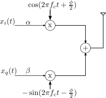
Figure : IQ modulator with gain and phase imbalance
The output signal is,
.
Considering an ideal IQ demodulator multiplying the received signal with
and
respectively,
.
.
Ignoring the common term and writing the base band equivalent form,
.
This is the model for transmit IQ imbalance.
Image Rejection Ratio (IMRR) with transmit IQ imbalance
By sending a complex sinusoidal , and by taking ratio of the power of the signal at the image frequency
and desired frequency
, the image rejection ratio can be computed.
Let and correspondingly,
and
.
Finding the component
To find the component, multiply the received signal
with
and integrate over period
.
The power of the component is,
Finding the component
To find the component, multiply the received signal
with
and integrate over period
.
The Image Rejection Ratio (IMRR) is
.
Substituting and
with variable
and
, the equation simplifies to,
.
A useful approximation to IMRR
When there is no phase imbalance i.e , the equation reduces to,
.
When there is no gain imbalance i.e , the equation reduces to,
.
As these two are independent, they can be added to give an approximate value of Image Rejection Ratio.
Summarizing, the Image Rejection Ratio for a given value of gain imbalance and phase imbalance
is,
.
Simulation Results
Simple Matlab/Octave code plotting the simulated and theoretical values of Image Rejection for different values of gain and phase imbalance.
clear; close all

N  = 64;
fm = 2;
gammadB_v = [-3:.1:3];
phiDeg_v  = [-6:.2:6];
[tt gammadB_zeroIdx ] = min(abs((gammadB_v-0)));
[tt phiDeg_zeroIdx  ] = min(abs((phiDeg_v-0)));

for (ii = 1:length(gammadB_v))
   for (jj = 1:length(phiDeg_v))
      gammadB    = gammadB_v(ii);
      phiDeg     = phiDeg_v(jj);
      gammaLin   = 10^(gammadB/20);
      phiRad     = phiDeg*pi/180;
      epsilonLin = gammaLin -1 ;

      % transmitted signal
      xt        = exp(j*2*pi*fm*[0:N-1]/N);
      % received signal with IQ imbalance
      xht_re    = gammaLin*cos(phiRad/2)*real(xt) + sin(phiRad/2)*imag(xt);
      xht_im    = gammaLin*sin(phiRad/2)*real(xt) + cos(phiRad/2)*imag(xt);
      xht       = xht_re + j*xht_im;

      % taking ifft() to find the +fm and -fm components
      yF        = fft(xht,N);
      y_pfm     = yF(fm+1);
      y_nfm     = yF(N-fm+1);

      est_imrr_lin    = (abs(y_nfm)./abs(y_pfm))^2;
      theory_imrr_lin = (gammaLin^2 + 1  - 2*gammaLin*cos(phiRad))./(gammaLin^2 + 1  + 2*gammaLin*cos(phiRad));
      approx_imrr_lin = (epsilonLin^2 + phiRad^2)/4;

      est_imrr_dB(ii,jj)    = 10*log10(est_imrr_lin);
      theory_imrr_dB(ii,jj) = 10*log10(theory_imrr_lin);
      approx_imrr_dB(ii,jj) = 10*log10(approx_imrr_lin);
   end
end

figure
plot(gammadB_v,theory_imrr_dB(:,phiDeg_zeroIdx),'bs-'); hold on
plot(gammadB_v,est_imrr_dB(:,phiDeg_zeroIdx),'md-');
plot(gammadB_v,approx_imrr_dB(:,phiDeg_zeroIdx),'gx-');
xlabel('gain imbalance, dB'); ylabel('image rejection, dB'); grid on;
legend('theory','estimated','approx')
title('Image Rejection Ratio with gain imbalance alone');
axis([-3 3 -50 -10]);

figure
plot(phiDeg_v,theory_imrr_dB(gammadB_zeroIdx,:),'bs-'); hold on
plot(phiDeg_v,est_imrr_dB(gammadB_zeroIdx,:),'md-');
plot(phiDeg_v,approx_imrr_dB(gammadB_zeroIdx,:),'gx-');
xlabel('phase imbalance, degree'); ylabel('image rejection, dB'); grid on;
legend('theory','estimated','approx')
title('Image Rejection Ratio with phase imbalance alone');
axis([-6 6 -50 -20]);
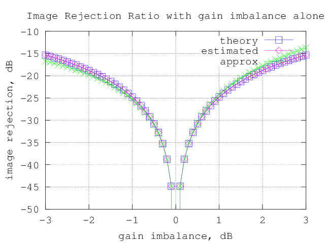
Figure : Image Rejection Ratio (IMRR) with gain imbalance alone
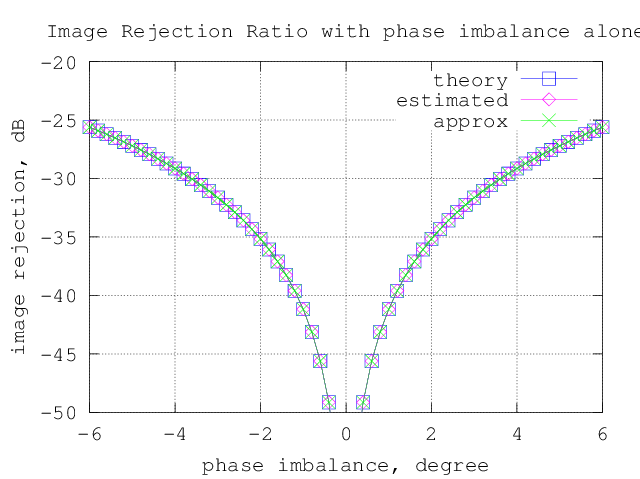
Figure : Image Rejection Ratio (IMRR) with phase imbalance alone
Observations
1) The approximate expression holds good for reasonable values of gain and phase imbalance.
2) As a rule of thumb, the following numbers are useful :
– For 1 degree of phase imbalance, the Image Rejection Ratio (IMRR) is around -41dB
– For 1dB of gain imbalance, the Image Rejection Ratio (IMRR) is around -25dB
References
[1] Cavers, J.K.; Liao, M.W.; , “Adaptive compensation for imbalance and offset losses in direct conversion transceivers,” Vehicular Technology, IEEE Transactions on , vol.42, no.4, pp.581-588, Nov 1993 doi: 10.1109/25.260752
[2] Table of trignometric identities http://www.sosmath.com/trig/Trig5/trig5/trig5.html