Oscillators are used in typical radio circuits to drive the mixer used for the up-conversion or down-conversion of the passband transmission. Ideally, the spectrum of the oscillator is expected to have an impulse at the frequency of oscillation with no frequency components else where. However the spectrum of practical oscillators do have spectrum skirts around the oscillation frequency caused due to phase noise. This post discuss about the phase noise of oscillator and the metrics used to specify it.
Oscillator spectrum
Consider the noisy output of an oscillator which has both amplitude noise and phase noise
.
.

Figure : Spectrum of ideal and practical oscillators
Typically, any perturbations to the amplitude gets rejected by the oscillator circuit itself (due to the feedback path in the oscillator). However, any perturbation on the phase does not get corrected and it persists.
Power spectral density of the phase )
The noise on the phase can be modeled to have a a step function impulse response for a noise perturbation , i.e.
.
The single sided power spectral density of the phase is,
.
This means that if :
a) is caused by white noise, then
b) is caused by flicker
noise , then
and so on.
Power spectral density of the voltage signal )
Given that the power spectral density of phase is difficult to observe directly, one might alternatively be interested in the power spectral density of the noisy oscillator out .
Using the equations (9),(11) in Introduction to RF simulation and its application, Ken Kundert :
The power spectral density of is,
,
where
are Fourier coefficients of
and
is a constant.
Given that only frequencies at is needed, this simplifies to
.
Substituting , the equation simplifies to,
.
Note : The spectrum follows the Lorentzian function
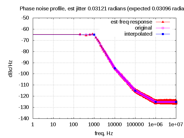
It is a typical metric to report the single side band phase noise power to the power of the carrier and represent as,
.
From Section 10.8 in Microwave Circuit Design Using Linear and Nonlinear Techniques, George D. Vendelin, Anthony M. Pavio, Ulrich L. Rohde
is the ratio of noise power in 1Hz bandwidth (BW) at offset
from carrier to carrier signal power.
Typically is expressed in dBc/Hz i.e deciBels relative to carrier per Hertz. As expected, having a higher phase noise in the signal does not increase the total power. A signal with higher phase noise will have lesser power near
and will be having a wide spectrum around the carrier. Conversely, a signal with lower phase noise has a sharper peak at the carrier with less skirts.
It can be shown that the integral of over all frequencies result in unity.
.
Matlab example
The following code snippet plots the for
and three different values of
.
close all; clear all;
fc = 500;
f  = [1:.1:1000];

c1  = 2*1e-5; f1b = c1*pi*fc^2; L1f = 1/pi*f1b./(f1b^2 + (f-fc).^2);
c2  = 1e-5; f2b = c2*pi*fc^2; L2f = 1/pi*f2b./(f2b^2 + (f-fc).^2);
c3  = 0.5*1e-5; f3b = c3*pi*fc^2; L3f = 1/pi*f3b./(f3b^2 + (f-fc).^2);

plot(f,L1f,'bs-'); hold on;
plot(f,L2f,'mp-'); plot(f,L3f,'gx-');
xlabel('freq, Hz'); ylabel('L(f)');
title('L(f), ratio of noise power to carrier power');
axis([300 700 0 0.09]); grid on;
legend('c=2e-5','c=1e-5', 'c=0.5e-5');
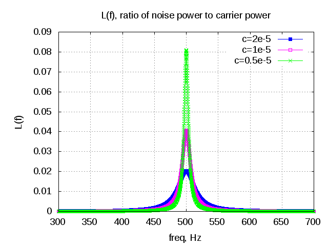
Figure: Plot of the noise power to carrier power for different values of c
As can be seen from the above figure, for higher values of , the spectrum becomes wider with lesser amplitude in the main lobe of the spectrum. Note that a wider main lobe does not increase the total power of the carrier.
The power spectral density can be approximated as,
.
The spectrum of with choosing
and dowconverting with an ideal osciallator tuned to
is plotted below.
clear all;
fc = 500; f  = [0.01:.01:100];
fb = 1/pi;
Lf = 1/pi*fb./(fb^2 + (f-fc+fc).^2);
Lf_approx = 1/pi*fb./(f-fc+fc).^2;

semilogx((f),10*log10(Lf),'bs-'); hold on;
semilogx((f),10*log10(Lf_approx),'rp-');
xlabel('freq, Hz'); ylabel('L(f), dBc/Hz');
title('L(f), ratio of noise power to carrier power');
legend('L(f)','L(f) approx');
axis([0.01 100 -50 10]); grid on;
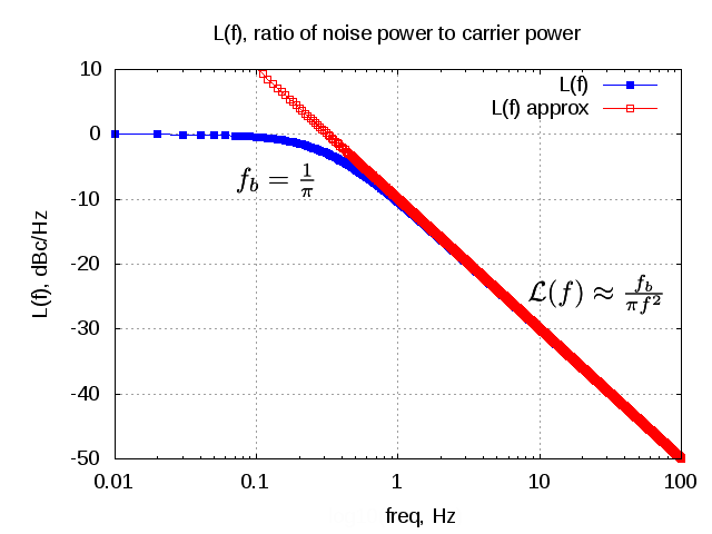
Figure : Normalized power spectral density
Relationship between }) and
and })
It can be seen that grows unbounded as frequency tends towards the carrier frequency, i.e.
as
.
However, the spectrum of the voltage signal is bounded.

Figure : Oscillator phase and voltage spectrum
From equation (16) in Introduction to RF simulation and its application, Ken Kundert, for ,
.
Note :
Did not fully appreciate the physical significance of having this relationship true only for frequencies . Anyhow a small proof for the above relationship assuming that the phase noise signal is a sinusoidal is given below.
Consider that the phase noise signal is a sinusoidal i.e.
.
The spectral density of the phase is,
.
The noisy carrier signal is,
Assuming is small,
and
.
With this the equation simplifies to,
.
The ratio of the single side band power to the carrier power is,
.
Matlab script (phase modulation)
% Matlab script showing the spectrum of a phase modulated carrier
clear all; close all
n_fft = 1024;
fc = 50; fs = 1024;
ts = [0:1023]/fs;
Ac = 2; Am = 0.2; fm = 10;
ct   = Ac*cos(2*pi*fc*ts); % carrier
phit = Am*sin(2*pi*fm*ts); % modulating signal
vt   = Ac*cos(2*pi*fc*ts + phit); % phase modulated carrier
cf = 1/(n_fft)*fft(ct,n_fft);
vf = 1/(n_fft)*fft(vt,n_fft);
plot([-512:511]*fs/1024,10*log10(abs(fftshift(vf)).^2),'mx-')
hold on;
plot([-512:511]*fs/1024,10*log10(abs(fftshift(cf)).^2),'bs-');
axis([0 100 -50 10]); grid on;
xlabel('freq, Hz');
ylabel('power spectral density, dB')
title('spectrum plot');
legend('phase modulated carrier','un modulated carrier');
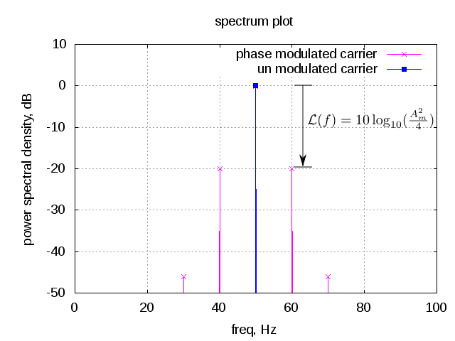
Figure : Phase modulated carrier
For the above example, with respect to the carrier the side lobes at are
down. There are more side lobes at
and further multiples of
, which can be ignored assuming that
is small.
Summary
a) The power spectral density of phase is related to the spectrum of the noise perturbation as
b) Phase noise typically can be modeled to have a Lorentzian spectrum and the phase noise relative to the carrier is typically is expressed in dBc/Hz i.e deciBels relative to carrier per Hertz
c) The power spectral density of the phase and
are related as,
.
References:
a) Introduction to RF simulation and its application, Ken Kundert, Version 2, 23 April 2003
b) wiki entry on Lorentzian function

Thanks
Good Information..