In the post on transmit pulse shaping filter, we had discussed pulse shaping using rectangular and sinc. In this post we will discuss about optimal receiver structure when pulse shaping is used at the transmitter. The receiver structure is also called as matched filter. For the discussion, we will assume rectangular pulse shaping, the channel is AWGN only and the modulation is BPSK.
Transmitter
The simplified transmitter structure is as shown below:

Figure: Transmit block diagram
The sequence of operation are as follows:
a). The random binary data comes as input to the the BPSK modulator circuit.
b). The BPSK modulator maps bits to symbols i.e bit0 to -1 and bit1 to +1
The sequence of transmit symbols maybe visualized as follows.
Figure: Transmit symbols for baseband PAM transmission
c). The upsampling block (the block with upward arrow) insert zeros between the samples based on the oversampling factor. For example, if the oversampling factor is 4, the block inserts 3 zeros between samples.
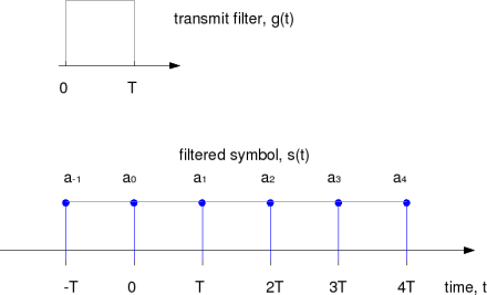
d). The last block in the chain is the filter, where the upsampled sequence is convolved with the filter. In this example, we have assumued rectangular filtering (also known as zero order hold), i.e. to repeat the current symbol till the next symbol arrives and so on. Mathematically, the filter can be represented as,
.
The filtered waveform can be as shown below.
Figure: Baseband PAM transmisison with rectangular filtering
The transmit spectrum assume that the symbol duration is shown below.
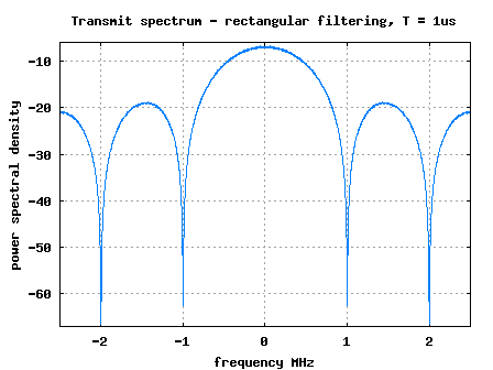
Figure: Transmit spectrum for rectangular matched filter
Matched filter Receiver
The filter having an impulse response is called a matched filter of
.

Figure: Matched filter response for a rectangular pulse shaping filter
In this example, as is a rectangular function, the mtched filter is also rectangular.
We pass the received signal through the matched filter
. The output of the convolution peaks at time
and we sample the at that time instant to perform the demodulation.
Further, if the filtered transmit signal is corrupted by noise, the filter with impulse response matched to
maximizes the output Signal to Noise Ratio. The proof for this claim is detailed in Chapter 5.1.2 Matched Filter Demodulator in Digital Communications by John Proakis.
Simulation Model
The Matlab/Octave script performs the following
(a) Generate random binary sequence of +1’s and -1’s.
(b) Upsample by inserting zeros and the convolve with rectangular filter
(c) Add white Gaussian noise.
(d) Convolve the received samples with matched filter, and extract output at time T
(e) Perform hard decision decoding and count the bit errors
(f) Repeat for multiple values of and plot the simulation and theoretical results.
Click here to download Matlab/Octave script for computing the BER for BPSK modulation in AWGN only with using rectangular pulse shaping at the transmitter and corresponding matched filter
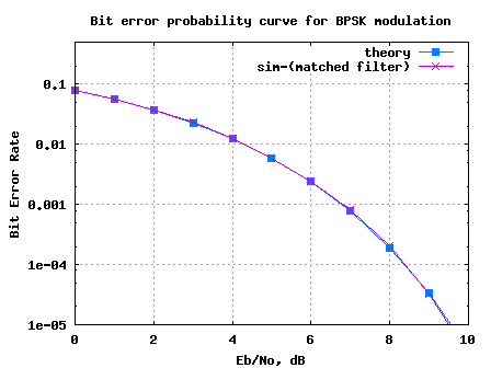
Figure: BER plot for BPSK with rectangular pulse shaping and matched filtering
Observations
Can see that the simulated results are in good agreement with the theoretical BER results for BPSK in AWGN in AWGN.

HELLO SIR,
we r doing project on modulation and demodulation of OFDM signal.
and having problem in QAM modulation.can u help us ???
we shall b very thankfull to u
nabil akram
@nabil: For posts on general M-QAM modulation with OFDM, please check out
https://dsplog.com/2012/01/01/symbol-error-rate-16qam-64qam-256qam/
i didnot get the concept why we use upsampling
@comm-eng: at a sampling frequency fs, we are limited to ‘seeing’ frequencies from [-fs/2 to fs/2). Typically, if we wish to see a higher frequency range, upsampling is used.
hello sir . i have question .
why the BER as function of SNR don’t change with filter shaping and without it .i think the fitter shaping reduce ISI so reduce BER,
i simulated the BER of Bpsk and Qpsk with and without the raised cosine filter but the result is almost the same , help me please
@abdou: To understand the effect of ISI, compute the error vector magnitude (EVM) between the received symbol and transmitted symbol for the two cases. If the EVM is below -30dB or so, it will have negligible impact on the BER for BPSK/QPSK (which has a 10^-4 ber at 12dB ish Eb/N0).
plz help me to make ISI channel
@jaspreet: Please check out posts under
https://dsplog.com/category/channel/
Hello sir,
about the awgn…Why don’t we use awgn() function of matlab directly to the signal?
about the rectangular shaping filter…Why don’t we use rectpulse() of matlab too instead of upsampling with zeros?
Thank you..
@Sapphire: No special reason, personal choice. I wish to use the bare minimum build blocks, so that I understand each function better 🙂
hello sir…
how to downsample the received UWB signal ??kindly help us with matlab code sir…
@Uma: Sorry, I have not tried modeling UWB signals
hello sir,
we r doin final year project.. sir please can you help us to downsample the received uwb signal.. kindly send us the matlab code for that sir..
@jennifer: Sorry, I have not tried modeling UWB signals. However,
for downsampling by factor of 2, take one sample every two samples;
for downsampling by factor of 3, take one sample every three samples; and so on
I have one question, how can we do the mapping for 2-PPM, I mean If we have ‘0’ bit to transmit, map the rectangular pulse at 01(decimal 1) for the first time slot and if we have ‘1’, map the rectangular pulse at 10(decimal 2) for the 2nd time slot. if you advise me
@Amjad: Seems you are looking for BPSK transmission? https://dsplog.com/2007/08/05/bit-error-probability-for-bpsk-modulation/
hello sir,
I’m doing receiver design of Cdma communications, i need to design matched filter for that can help regarding its internal structure…
@vasanth: You might want to know the transmit pulse shaping filter which was used. You may try with rectangular, raised cosine, Gaussian pulse shapes.
hi…i just went thru ur code….
what if i use ral noise insteadf of complex noise,,,,,
performance should change or not??
I am getting changed performance….can u tell whtz the reason??
@vikas: If its BPSK modulation, and you do the scaling correctly, there should not be any difference in performance.
Sorry~ I already solving it yesterday, the fading channel
have to assuming “slow fading” , a symbol was affected
by a fading.
thank you~! this is a very good blog!
@Wig: Glad to hear that. Good luck for your future algorithm investigations.
hello ~
I tried this method , BPSK with MF over “fading channel”, it has a big
problem, if I change sampling time (ts), then the BER change,too! I
think its power need normalize? But I’m not sure…
I wish you can solve my problem. thanks a lot!!
@Wig: If BER is changing with sampling time, quite likely its a power normalization issue. Hope the code in the attached post might be of help to you.
Another question, in the recieving side the code
ySamp = yFilt(os:os:N*os); % sampling at time T
why not using
ySamp = yFilt(1:os:N*os);
@Saria: We are taking at the output of matched filter. For optimal performance, we need to let the matched filter run for the time ‘os’ and then tap the value. If we were to do as what you have proposed, then our performance will be poorer. You can experiment in the code and try.
I think you are trying to pick sample for the symbol with max energy, am I right? Thats what downsampling will do in matlab. If we have more than 1 samples per symbol we pick max sampling while downsampling or we could have picked avg of all, but this would be a poor performance as you rightly said.
regards
@Khan: The idea is take all the information which is available i.e. for a rectangular pulse shaping, we accumulate over the rectangular window and use.
Dear Khrishna, thank you forever! you are really helping us. I would like to ask in the transmit filter you multiplied the result of convolution by 1/sqrt(os), why? and why you didnot use this factor in the matched filter at the reciever side?
@Saria: The multiplication by 1/sqrt(os) is to normalize the transmit power to 1. Recall: We are sending the same information os times. We do this at the transmitter, because we want to scale the transmit power accordingly to make our Eb/N0 definition correct.
At the receiver, we do not have such constraints.
Hi Krishna,
You are a great help, Just to check I have calculated the power for sFilt which is
sum(abs(sFilt))/length(sFilt)
this doesnt c0me to 1, am I doing something wrong?
regards
@Khan: You might want to do sum of the powers and not sum of absolute values.
octave:16> sum(abs(sFilt).^2)/length(sFilt)
ans = 0.20000
I think 0.2 is because of oversampling ratio of 1/5.
I have two questions,
1) Why do we need to upsample?
2) Why is the impulse response of the matched filter for g(t) equal to g(T-t)? I know we always use this kind of relation when ever we write an equation for a signal recieved at the receiver. Maybe I dont understand the “(T-t)” thing
@communications_engineer: My replies
1) When doing digital domain, the frequencies which we can ‘see’ are limited by the sampling rate. For eg, if the sampling rate is fs, the frequencies which we can see is from [-fs/2 to fs/2). Typically, when doing digital frequencies, you would want to control the frequency response over a wider frequency range (else spectrum just repeats as +/-k*fs), hence we do upsampling.
2) g(T-t) stands for time reversed version of g(t). Does that help?
So we take the upsampling factor that is equal to the twice of the edge frequency till which we want to control the frequency response – right?
@communications_engineer: Correct
Hello Krishna, another gem of an article. We all owe you for the work that you are doing.
May I suggest/request you that please extend this post as a series where we discuss Maximum likelihood, Log-likelihood and MAP detection
Or you explain the Single user detection and Multiuser detection. Most strategies used here, we have already discussed in MIMO systems like (ZF, MRC, EQC, MMSE, SIC, PIC) so please put some tutorials over here for CDMA before any other topic.
Thanks again Krishna
@communications_engineer: Kind words indeed. Thanks. All the above topics are there in my TO-DO list. Hopefully, slowly we cover them….