Typical communication systems use I-Q modulation and we had discussed the need for I-Q modulation in the past. In this post, let us understand I-Q imbalance and its effect on transmit signal.
I-Q modulation and demodulation
The typical I-Q modulation and demodulation is as shown in the figure below. Consider that the information to be transmitted is a complex signal,
.
At the output of I-Q modulation transmitter is,
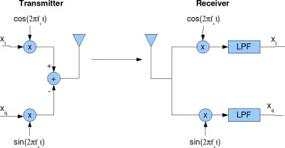
Figure: I-Q modulation Transmitter and receiver
At the transmitter, the information is sent on
and
is sent on
.
At the receiver, we multiply the signal with
and
followed by low pass filtering (LPF) to extract,
and
respectively.
From trigonmetric identies,
,
,
.
The math for extracting the information at the receiver is as follows:
.
Similarly for the Q-arm,
.
Ignoring the scaling factor of 1/2, we are able to recover both and
.
Phase imbalance in IQ modulation
In an ideal I-Q modulator, the phase difference between the signals used for modulating the I arm and Q arm is 90degrees, resulting in using and
for sending
and
.
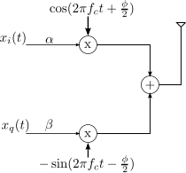
When there is phase imbalance, the phase difference might not be exactly 90 degrees. We can consider that is used for sending
and
for sending
.
Amplitude imbalance in IQ modulation
When there is amplitude imbalance, there is small variation in the amplitude of thse sine and cosine arms in the modulator. This can be modelled as using for sending
and using
for sending
, where
is constant lying between 0 and 1.
The transmit signal including the effect of phase and amplitude imbalance is,
.
Received signal with IQ imbalance in transmitter
Assuming that we have ideal IQ demodulator ie. at the receiver, we multiply the signal with
and
followed by low pass filtering (LPF) to extract,
and
respectively.
.
.
As can be observed from the above equations, the desired signal is distorted due to the presence of IQ imbalance.
Effect on spectrum due to I-Q imbalance
To understand the effect of I-Q imbalance on the transmit signal, let us consider that the transmitted signal is i.e,
and
From the post on negative frequency, we know that such signal has a frequency component at and NO frequency component at
.
In the presence of I-Q imbalance at the transmitter, the received signal is,
and
.
Click here to download Matlab/Octave script for plotting receive spectrum with transmit IQ imbalance
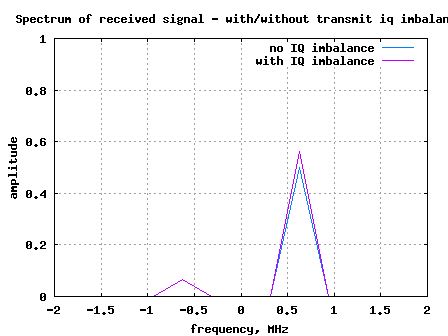
Figure: Spectrum of received signal in the presence of IQ imbalance at the transmitter
It is reasonably intuitive to see that the received signal has frequency components at and also at
. The component at
was introduced due to I-Q imbalance.
Update : Click here for the derivation of Image Rejection Ratio (IMRR) with transmit IQ gain/phase imbalance


Nice post…
informative too…
Thanks
Hi Krishna,
Could you please let me know how should I use LPF on I and Q components after down conversion?
@sudhan: The LPF is applied independently on I and Q channel
Hi Krishna,
I have a question,
I implement QPSK modulation in matlab, that have:
– Bit rate : Rb = 10kbps
– Carrier frequency: 10Mhz
– Sampling frequency: 80khz
Is it right to choose variables like that?
and i don’t know how to set up a low pass filter with cutoff freequency = 10mhz,
Thanks for your help!
@Tuyen Tran:
a) The concept of sampling is notional in matlab. Your above parameters looks fine.
b) Try seeing the help of any IIR filters like butterworth, chebyshev etc
Thanks for your reply!
Hi Krishna,
Please let me know how to compensate the IQ imbalance in a OFDMA system.. we are doing real time project and we are passing data in one subcarrier in the receiver if we take fft of the data we are seeing some magnitude in the negative frequency also .. as ur matlab code demonstrates
@Ananth: Well, at the transmitter you can put a butterfly like structure where you artificially introduce gain and phase imbalance in digital such that the pre-distorted digital IQ imabalance nullifies the RF IQ imbalance. From, googling you should be able to get good pointers.
great !!
i have a question please!!
in my work,i have to deal with I-Q ambalance and the output is sent to a “complex to a real image” wha is the point of this ?
regards
@yasmine: Sorry, I did not understand your query.
Hello,
I have a question:Do the I&Q-Components (at the Reciever) have only 1 frequenz or they can have various frequenz (bandwidth) ?
I have a Radio Reciever , at the Output is I-Q Components over time . the Reciever range is from 0-30Mhz. i want to write a program that show a realtime FFT plot.
Thank in advance
Kukku
@Kukku: Typically the I/Q signals on a receiver will have various frequencies. You can do a close to real time FFT plot by taking a chunk of samples (64/128 etc), doing an FFT on them and plotting.
Oh, I’m sorry, I mean of course the input signal x. It is firstly up-converted and then down-converted to the orginal baseband. As a result we get xHatSC_NoIQ.
In my opinion the both signals shouldn’t differ, or am I missing something ?
Thank you !
Sorry for the double posting but I think I see it now. There is a mirror signal part on the negative frequency, which i didnt see because of scaling u have used. So, in order to recover the input signal properly I have to use a low pass filter, right ?
And one more question, if I up-convert the input signal to the carrier frequency bigger than the sampling frequency, do I have to increase the sampling frequency at the receiver ?
Thank you !
@joel: My replies:
1/ Yes, you are right that we need a filter. For additional thoughts, plz look at my response to your previous comment
2/ Yes. Note that with a sampling frequency of fs, the frequencies which we can ‘see’ are from [-fs/2 to fs/2). Any frequency outside this range will fold back into this range.
@joel: Yes, as you rightly commented later, we need a low pass filter to get back the original signal. And the explanation for that is as follows:
The signal yNoIQ has spectrum at [fc+fsc] and -[fc+fsc]. After we did the downconversion, the spectrum at -[fc+fsc] went to -[2fc+fsc] and spectrum at [fc+fsc] came to [fsc]. Hence we need to remove -[2fc+fsc] to see the original signal.
Hope this clarifies.
Dear Krishna,
after running the script I observed that the cNoIQ and xHatSC_NoIQ differ considerably. What is the reason for that ? After the up and down conversion they shall be almost the same… Is the sample time the problem here ?
Best Regards,
Joel
@joel: Well, cNoIQ is the carrier and xHatSC_NoIQ is the modulated waveform, no?
i am very thankfull to u .your knowledge has helped me a lot in doing my final year project.
@jamil: Glad to be of help. 🙂
Thanks for your information about it……
nice post…..
@Abdul: Thanks 🙂
very nice and informative.
neat presentation. forms the basis for further exploring this.