Coding is a technique where redundancy is added to original bit sequence to increase the reliability of the communication. Lets discuss a simple binary convolutional coding scheme at the transmitter and the associated Viterbi (maximum likelihood) decoding scheme at the receiver.
Update: For some reason, the blog is unable to display the article which discuss both Convolutional coding and Viterbi decoding. As a work around, the article was broken upto into two posts.
This post descrbes the Viterbi decoding algorithm for a simple Binary Convolutional Code with rate 1/2, constraint length and having generator polynomial
. For more details on the Binary convolutional code, please refer to the post – Convolutional code
Viterbi algorithm
As explained in Chapter 5.1.4 of Digital Communications by John Proakis for optimal decoding for a modulation scheme with memory (as is the case here), if there are
coded bits, we need to search from
possible combinations. This becomes prohibitively complex as
becomes large. However, Mr. Andrew J Viterbi in his landmark paper Error bounds for convolutional codes and an asymptotically optimum decoding algorithm, IEEE Transactions on Information Theory 13(2):260–269, April 1967 described a scheme for reducing the complexity to more managable levels. Some of the key assumptions are as follows:
(a) As shown in Table 1 and Figure 2 (in the article Convoutional Code) any state can be reached from only 2 possible previous state.
(b) Though we reach each state from 2 possible states, only one of the transition in valid. We can find the transition which is more likely (based on the received coded bits) and ignore the other transition.
(c) The errors in the received coded sequence are randomly distributed and the probability of error is small.
Based on the above assumptions, the decoding scheme proceed as follows: Assume that there are coded bits. Take two coded bits at a time for processing and compute Hamming distance, Branch Metric, Path Metric and Survivor Path index for
times. Let
be the index varying from 1 till
.
Hamming Distance Computation
For decoding, consider two received coded bits at a time and compute the Hamming distance between all possible combinations of two bits. The number of differing bits can be computed by XOR-ing
with 00, 01, 10, 11 and then counting the number of ones.
is the number of 1’s in
is the number of 1’s in
is the number of 1’s in
is the number of 1’s in
Branch Metric and Path Metric Computation
As stated prior, each state can be reached from two possible states (shown by red and blue lines respectively). Branch metric is the sum of the path metric of the previous state and the hamming distance required for the transition. From the two avaiable branch metrices, the one with minimum branch metric value is chosen. This operation is also referred to as Add Compare and Select (ACS) unit.
Note:
1. Typically, Convolutional coder always starts from State 00. The Viterbi decoder also assumes the same.
2. For index = 1, branch metric for State 00 (from State 00) branch and State 10 (from State 00) can only be computed. In this case, path metric for each state is equal to branch metric as the other branch is not valid.
3. For index = 2, branch metric for State 00 (from State 00) branch, State 01 (from State 10), State 10 (from State 00) and State 11 (from State 10) can only be computed. In this case too, path metric for each state is equal to branch metric as the other branch is not valid.
4. Starting from index =3, each state has two branches and the need to do Add Compare and Select arises.
5. Its possible that two branch metrices might have the same value. In that scenario, we can chose one among the the branches and proceed.
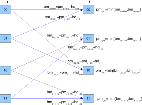
Figure: Branch Metric and Path Metric computation for Viterbi decoder
State 00 can be reached from two branches
(a) State 00 with output 00. The branch metric for this transition is,
.
(b) State 01 with output 11. The branch metric for this transition is,
.
The path metric for state 00 is chosen based which is minimum out of the two.
The survivor path for state 00 is stored in survivor path metric.
State 01 can be reached from two branches:
(c) State 10 with output 10. The branch metric for this transition is,
(d) State 11 with output 01. The branch metric for this transition is,
The path metric for state 01 is chosen based which is minimum out of the two.
.
The survivor path for state 01 is stored in survivor path metric.
.
State 10 can be reached from two branches:
(e) State 00 with output 11. The branch metric for this transition is,
(f) State 01 with output 00. The branch metric for this transition is,
The path metric for state 10 is chosen based which is minimum out of the two.
.
The survivor path for state 10 is stored in survivor path metric.
.
State 11 can be reached from two branches:
(g) State 10 with output 01. The branch metric for this transition is,
(h) State 11 with output 10. The branch metric for this transition is,
.
The path metric for state 11 is chosen based which is minimum out of the two.
The survivor path for state 11 is stored in survivor path metric.
.
Traceback Unit
Once the survivor path is computed times, the decoding algorithm can start trying to estimate the input sequence. Thanks to presence of tail bits (additional
zeros) , it is known that the final state following Convolutional code is State 00.
So, start from the last computed survivor path at index for State 00. From the survivor path, find the previous state corresponding to the current state. From the knowledge of current state and previous state, the input sequence can be determined (Ref: Table 2 Input given current state and previous state). Continue tracking back through the survivor path and estimate the input sequence till index = 1.
| ip, if previous state | ||||
| current state | 00 | 01 | 10 | 11 |
| 00 | 0 | 0 | x | x |
| 01 | x | x | 0 | 0 |
| 10 | 1 | 1 | x | x |
| 11 | x | x | 1 | 1 |
Table 2: Input given current state and previous state
Simulation Model
Octave/Matlab source code for computing the bit error rate for BPSK modulation in AWGN using the convolutional coding and Viterbi decoding is provided. Refer to the post on Bit Error Rate (BER) for BPSK modulation for signal and channel model.
Note: Since 2 coded bits are required for transmission of each data bit, the relation between coded bits to noise ratio with bits to noise ratio
is
.
The simulation model performs the following:
(a) Generation of random BPSK modulated symbols +1’s and -1’s
(b) Convolutionally encode them using rate -1/2, generator polynomial [7,5] octal code
(c) Passing them through Additive White Gaussian Noise channel
(d) Hard decision demodulation on the received coded symbols
(e) Received coded bits are passed to Viterbi decoder
(f) Counting the number of errors from the output of Viterbi decoder
(g) Repeating the same for multiple Eb/No value.
Click here to download Matlab/Octave script for computing BER with Binary Convolutional code and Viterbi decodig for BPSK modulation in AWGN channel
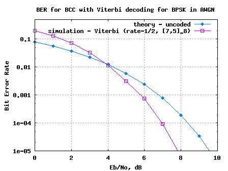
Figure 3: BER plot for BPSK modulation in AWGN channel with Binary Convolutional code and hard decision Viterbi decoding
Observations
1. For lower regions, the error rate with Viterbi decoding is higher uncoded bit error rate. This is because, Viterbi decoder prefers the error to be randomly distributed for it work effectively. At lower
values, there are more chances of multiple received coded bits in errors, and the Viterbi algorithm is unable to recover.
2. There can be further optimizations like – using soft decision decoding, limiting the traceback length etc. Those can be discussed in future posts. 🙂
References
Tutorial on Convolutional Coding with Viterbi Decoding – Mr. Chip Fleming
Sir,
We want to simulate turbo decoding using SOVA algorithm,So will u please send me matlab codings for SOVA algorithm.
@kavitha: sorry, i have not discussed turbo codes in the blog yet.
Sir,
Thanks for your post.
I need your help to make viterbi decoder in Matlab for convolutional encoder 2/3. i will to apply for TCM 8psk
thanks
@Popy: Thanks. Good luck
Hi, I want to know that what will ipLUT do in the code?
@Rakesh: I recall it is storing Table 2: Input given current state and previous state
in the program I’m not able to understand the following line.
rv = kron(ones(4,1),r);
What will this do? In fact, we need to calculate the Hamming Distance between received codeword and the branch output.
Do Viterbi Decoder needs to be aware of Modulation scheme? I’m using QPSK modulation.
@Jayesh: Replies:
a). kron is doing the conversion of a vector into a matrix.
r = [1 0]
rv = kron(ones(4,1),r)
rv =
1 0
1 0
1 0
1 0
b) the viterbi decoder need not be aware of the modulation scheme.
however for the soft decision we need to feed the soft information according to the modulation scheme.
for some more posts on viterbi decoder, please look at
https://dsplog.com/tag/viterbi
Hi Krishna,
Do you implement hard decision viterbi on c/c++? If so, could you please contakt me 🙂
Thanks a lot!
@Yuriy: Please take a look at
https://dsplog.com/2009/08/21/matlab-or-c-for-viterbi-decoder/
Hello,
I run this code in matlab . And it Doesn’t Work the message of matlab is :
??? Error using ==> conv2
First and second arguments must be single or double.
Error in ==> conv at 39
c = conv2(a(:),b(:),shape);
Error in ==> Untitled at 20
cip1 = mod(conv(ip,[1 1 1 ]),2);
PLEASE HELP. What is the problem with code??????
@george: Where did you see the usage of conv2?
Try using this and edit in the original file:
% Transmitter
%ip = rand(1,N)>0.5; % generating 0,1 with equal probability
%Generate Random Data[i/p matrix..]
ip=zeros(1,64);
d=rand(1,64);
for i=1:64
if(d(i)>=0.5)
d(i)=+1;
else
d(i)=-1;
end
end
for i=1:64
ip(1,i)=d(i);
end
but the problem in the original code then pops up:
??? Index exceeds matrix dimensions.
Error in ==> Coded_nofinal_2 at 144
nErrViterbi(yy) = size(find([ip- ipHat_v(1:N)]),2)
Im using matlab and not octave.
@Anuj: Should be reasonably easy to figure out. Check out the size of ipHat_v to figure out why it is smaller than N
@george ,
do one thing: change cip1,cip2 as
cip1 = mod(conv(double(ip),[1 1 1 ]),2);
cip2 = mod(conv(double(ip),[1 0 1 ]),2);
amm……..
I don`t know why but the code I download from this page doesnt work.
nErrViterbi(yy) = size(find([ip- ipHat_v(1:N)]),2);
the dimensions of ipHat_v are smaller than N
Can you tell me how can I resolve this problem I just cant
@Rodrigo: Are you sure? I re-ran the code. It’s working.
sorry I just discover there was an error in mi matlab libreries
Hi Krishna…………..
i am trying to plot the graph of BER vs SNR for bayesian demodulation and QPSK demodulation. I have to analysis the performance for these two techniques. Could you please help me in this matter.
And, can you help in the matlab code for theoritical and pratical BER for QPSK.
With Regards,
sulav paudel
@Sulav: Hopefully the following post might be of help
a) BER of BPSK in AWGN
https://dsplog.com/2007/08/05/bit-error-probability-for-bpsk-modulation/
b) Symbol Error rate of QPSK in AWGN
https://dsplog.com/2007/11/06/symbol-error-rate-for-4-qam/
Hi Krishna,
Appreciate your efforts in the first place.
I have a question for you.. I would like to replace the Euclidean distance with another metric for non-gaussian noise cases.. for instance, I would like to use alpha-penalty function or known state maximum likelihood distance metric to enhance my decoder performance against impulsice noise..
how would you go about it?? does it change the way how you compute the soft inputs?? or changing only the distance metric is enough??
have you ever tried another metric for non-gaussian noise for your decoder??
thanx in advance,
TayyaR.
@guzeltayyar: I guess, one way is to give less weights to softbits affected by impulse noise. This can be done by scaling down those softbits. I have not tried any metric for non-gaussian noise.
Hi Krishna,
Thanks for your post.
I need your help in implementing this code when channel is AWGN+Rayleigh fading.
Kindly help me to tell what modifications are required in this program for soft decoding.
….
Keshav
@Keshav Kishore Jha: Need to have a multiplicative noise to model the Rayleigh channel. You may refer to examples @ https://dsplog.com/tag/rayleigh/
hi sir
i am a mtech student.. and i’m working on d project hand writing recognition using hidden markov model. here in this project 1st we extract the hand writing features and then should build the HMM model, after this we use viterbi algorithm for recognition and baum-welch alogrithm for training. so please can u help me in viterbi algorithm part…….?
@sujata.kamlapur: Does the Viterbi decoder code provided in this post help?
Hi,
In your code I see that the survivor path metric index you have calculated as minimum of the 2 paths. Some thing like this
case I : says idx
case II; you say it is idx+2.
I don’t understand this. What would it be if I am using 8PSK with 8 states ? I am not able to arrive at the idx thing for storing the path index. Could you please help me with that ?
Thanks,
Harish
@Harish: Well, I have assumed BPSK in this simulation. Even if you are using BPSK, I believe you might be passing on the received hard decision bits to the Viterbi decoder. So the underlying path metrics computation should still hold good. Agree?
It’s difficult to viterbi…
Help me, mt graduation of thesis.
Image(photo) processing/ Simulation to C++
@Hyunjin.Jang: Hope this post helps. Good luck.
Excellent tutorial. Thanks a lot.
BR,
Neo
can u send the vhdl and verilog coding for low-latency low-complexity architectres for viterbi decoder
@amudhan: sorry, i do not have vhdl/verilog code.
Hi kirishna
What can i do to write a simulation of Space Time Trellis code ?
if u have a matlab code please try to provide me.
Best Regards
Fateme
@fateme: Sorry, I have not tried modeling space time trellis code.
Hi,
Can you give me the best generator polynomials for various constraint lengths.
@arun: You may check the Chapter 8.2.5 in Digital Communications by John Proakis. That chapter has a list of generator polynomials for various code rates from 1/2, 1/3, 1/4, 1/5, 1/6, 1/7, 1/8 … for constraint length from K=3 to K=14.
What changes should I make for k=5, r=1/3 decoder?
@einstein: For k=1/5, r=1/3 the state transitions change. The branch metric and path metric computations needs to be changed accordingly.
Hi krishna,
Can you give the list of generator polynomials for various constraints lengths.
Ex: k=7 the Generator poly is 133 ,171
@arun: You may check the Chapter 8.2.5 in Digital Communications by John Proakis. That chapter has a list of generator polynomials for various code rates from 1/2, 1/3, 1/4, 1/5, 1/6, 1/7, 1/8 … for constraint length from K=3 to K=14.
Superb Explanation. Thumbs Up bro
@Zeeshan Sattar: Thanks pal.
Hi
I want to know for R=1/2 K=7 convolutional code which generator matrix is best.
Please tell me how can I get the answer.
Also I want to simulate convolutional coding with FSK.
Please tell me how to do it.
@chintu: My replies:
(1) From looking at the Table 8.2.1 in Digital Communications, Proakis, find that for K=7, the generator polynomial is {133,171}_octal. I think, reasearchers long back have tried simulating with different generator polynomails and the table listed in the book lists the best for each constraint length and rate combination.
(2) I have written a post on BER with FSK
https://dsplog.com/2007/08/30/bit-error-rate-for-frequency-shift-keying-with-coherent-demodulation/
Hope it should be reasonably easy for you to add convolutional coding + viterbi decoding to that script.
The generator matrix for the optimal code for above query if given a different value in Lin and costello ” error control coding”
which is (117, 155) octal.Please clarify.
Also how do I implement this R=1/2 K=7 convolution code in your convolution coding(r=1/2,k=3) script as it is designed for K=3 and can’t be generalized for K=7.
Please post a generalized script.
@chintu: My objective was to provide an example code for Viterbi decoder to help understand the concept. Am reasonably sure that once you understand the concept, the reader can easily extended to other cases. Good luck in your project work.
Hi krishna
I am doing viterbi decoder in verilog can you tell me from where i can get a code for reference
@ahmed: You may check
http://home.netcom.com/%7Echip.f/viterbi/fecbiblio.html
Hi,
It’s me again…. I hope to see the explanation on the soft decoding which can improve the situation.
Thanks.
@Allyson: You may refer to the post @
https://dsplog.com/2009/01/14/soft-viterbi/
Hi,
I use the Matlab function (bercoding) to simulate the coded-AWGN-BER. and for the decoding and encoding method I use matlab function as well (vitdec and convenc)… My simulated result is near to uncoded-AWGN-BER but not near to coded-AWGN.
Why is it so?
@Allyson: Quite likely a power normalization issue.
Hi Krishna,
Thanks for the reply. I am still facing an issue in the encoder part- When the bits are convolutionally coded, the coded bits together with the uncoded bits are mapped to a space to generate symbols. Till this point we deal wih the digital bitstream,but when this bitstream passes through the channel, AWGN noise(whose value is between 0 and 1 eg: 0.8)is added which is analog in nature. The problem is how to add analog noise to digital stream.Is it through D/A and A/D converters or quantization concept or the AWGN output is converted to digital stream?
@scorswiss: The AWGN noise (which can theoreticall be from -inf to +inf) is added between the DA/ and A/D. If I may
the chain will be as follows:
Bits -> convolutional coded bits -> constellation mapping -> filtering -> D/A –> Add Noise –> A/D –> constellation to bits -> Viterbi decoding
Alternatively we can use Soft decision decoding:
https://dsplog.com/2009/01/14/soft-viterbi/
Bits -> convolutional coded bits -> constellation mapping -> filtering -> D/A –> Add Noise –> A/D –> soft decision Viterbi decoding
Hope this helps.
Hello Krishna,
I want to develop a verification environment in Verilog for Viterbi decoder. I want a tested C model or Verilog model for the same.From where can I get it?
@scorswiss: In the posts I have provided a Matlab code for soft decision and hard decision Viterbi decoder for the rate 1/2 K=3 convolutional encoder. Maybe you can convert that to C and use.
hello , I am also looking for matlab code for k=3 and r=1/2 , I am writing VHDL code for it I cant find the code you post it for matlab could you tell me where exactly I can find it
thank you in advance
@setareh: The URL for the code is provided just above the BER plot.
hello!Kirishina u did it for BPSk modulation but how can i write a matlab code when the modulation is changed to QAM, QPSK ,16-QAM and 64-QAM?
Thank you!
can i get the vhdl code for k=7 and the inputs being 171 and 133 octal, with the rate=1/2
@Ricky: Sorry, we mostly discuss Matlab modeling here.
hey man i am looking for the same did you get it???
Hello! kirishna
what can i do to write a simulation of convolutionaly coded QAM, QPSK,16-QAM and 64-QAM signals and also Trellis coded MOdulation?if u have a matlab code please try to provide me.
Thanks
@Lealem: Trellis coded modulation – not yet. Hope to write soon. 🙂
Hi Krishna
Thanks for article on viterbi.I would like further articles discussing..
1> The following assumption :The errors in the received coded sequence are randomly distributed and the probability of error is small.
2> How you decide about traceback length? We can’t wait for all the input to be arrive before starting traceback.
3> For 11n what type of architecture is used for high throughput?
Regards
@Sandeep: Thanks. My replies:
1. If you recall, the decoding complexity is reduced in Viterbi algorithm by assuming that each state can be reached from only two possible states and only one of them is valid. However, if there are burst errors (or if the probability of error is high) then the above assumption becomes invalid. So, when we traceback we might not be able to decode correctly.
2. For the current simulation, I assumed that we wait till the end of all the coded bits to start traceback. As you said, in typical systems, we do not do that. We typically start the traceback much before. I will write a post on traceback length.
3. The Viterbi algorithm described in the post takes two coded bits and gives one data bit per iteration. However, we can write the transition table to take four coded bits and give out 2 data bits per iteration. This architecture allows one with a clock frequency limited system to have a higher throughput at the expense of extra hardware.
Hope this helps.
Hello! Kirishna
Thank you for ur matlab script Concerning convolutional coding. Do u have a matlab script which is used to simulate convolutional coded OFDM? an do u have also matlab script of convolutional coding that use a soft decision decoding algorithm? Thank you!!!
@Lealem: Thanks. Sorry, I have not yet written posts on using convolutional coding with OFDM. Maybe once I discuss interleaver, I will add a post on it.
I am writing a post on soft decision decoding, I just finished the simulation model. 🙂
Thank you! Kirishna
what can i do to write a simulation of convolutionaly coded QAM, QPSK,16-QAM and 64-QAM signals and also Trellis coded MOdulation?
Thanks
Hey Krishna,
I am writing a Viterbi decoding algorithm for a simple Binary Convolutional Code with rate 1/3, constraint length K=5, and having generator polynomial G=(25,33,37) in matlab . Can you please help.
@detito: Hopefully, the code in this post can help you as a reference.
Sir,
Sir,
We want to compute with binary convolutional code of rate=1/2, generator polynomial- [171, 133] Octal…..
Kindly help us pleaseeeeeeeee………