Coding is a technique where redundancy is added to original bit sequence to increase the reliability of the communication. In this article, lets discuss a simple binary convolutional coding scheme at the transmitter and the associated Viterbi (maximum likelihood) decoding scheme at the receiver.
Update: For some reason, the blog is unable to display the article which discuss both Convolutional coding and Viterbi decoding. As a work around, the article was broken upto into two posts. This post descrbes a simple Binary Convolutional Coding scheme. For details on the Viterbi decoding algorithm, please refer to the post – Viterbi decoder.
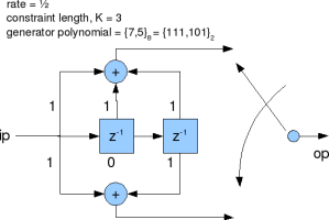
Chapter 8, Table 8.2-1 of Digital Communications by John Proakis lists the various rate 1/2 convolutional coding schemes. The simplest among them has constraint length with generator polynomial
. There are three parameters which define the convolotional code:
(a) Rate : Ratio of the number of input bits to the number of output bits. In this example, rate is 1/2 which means there are two output bits for each input bit.
(b) Constraint length : The number of delay elements in the convolutional coding. In this example, with there are two delay elements.
(c) Generator polynomial : Wiring of the input sequence with the delay elements to form the output. In this example, generator polynomial is . The output from the
arm uses the XOR of the current input, previous input and the previous to previous input. The output from the
uses the XOR of the current input and the previous to previous input.


salut, please Krishna I have to do a script to simulate QAM16 with convolutional code and viterbi decoder !
Please help me ! it is very important !
@marwa: Hope the post on Viterbi decoder and 16QAM bit error rate will be of help
https://dsplog.com/2009/01/04/viterbi/
https://dsplog.com/2008/06/05/16qam-bit-error-gray-mapping/
please provide the vhdl code for convolution encoder
@sirisha: sorry, i do not have it
sir pls give me suggestion regarding this how to implement in matlab:
MATLAB: Simulate the performance of a Viterbi decoder for the en-
coder
[
1 + D2 1 + D + D2
]
over an additive Gaussian noise channel
for BPSK modulated symbols. In your simulations assume the initial
state is the all-zero state, and run blocks of 1000 information bits per
block, terminating each block with two 0’s to drive the encoder into
the all-zero state. Plot the BER vs SNR.
@arnab: For some posts on Viterbi decoding with convolutional encoder, please check out
https://dsplog.com/2009/01/04/viterbi/
https://dsplog.com/tag/viterbi/
Hi
An ISI channel can be viewed as a convolutional encoder. when MMSE LE is used at the receiver the cascade of Channel and Equalizer is still not ISI free .
How can we apply viterbi decoder after the equalizer in this case.
Regards
mepal
@mepal: We can use the state transitions caused by the channel and use that to build a Viterbi decoder.
sir im doing project on error detection and correction using convolution code in fpga,,, can u pls help me … thanking u 🙂
@gopinath: I have not discussed anything about FPGA coding, but you can read up about Viterbi decoder at
https://dsplog.com/tag/viterbi
Hi Krishna;
I want to know how to prepare logic tables for a 1/3 convolution coder.
@Arpita: I believe you will be knowing the generator polynomial. From that one should be able to prepare the state transition table
Hi Krishna,
I’m totally messed up with Convolutional code.
I want to implement convo. encoder using K=3 with (7 , 5) generator. What is the rate of my problem. I have no idea what is my n an k.
I have refered many books and ended up being confused among symbols.
Kindly make me clear with K,k,n,M symbols.
@Ronak: Please refer Digital Communications by John Proakis
Also the post on Viterbi decoder also might be of help
https://dsplog.com/2009/01/04/viterbi/
hi,
I m doing project on implementation of turbo encoder using VHDL . Can i get information about turbo encoder?
I found in various places a table containing generator polynomials for convolutional encoding, specifically Table 1-“Generator Polynomials found by Busgang for good rate ½ codes” posted at http://www.complextoreal.com/convo.htm.
That table contains on the line Constraint length = 7 two identical polynomials, G1 = 110101 and G2 = 110101.
I guess this is not possible. The two polynomials must be different.
Does anybody knows the correct polynomials?
@Gheorge: I think that might be a typo. From Digital Communications by John Proakis, Table 8.2.1 , the generator polynomial in octal for constraint length 7, rate1/2 codes are:
a) 133_octal = 10000101_binary
b) 171_octal = 10101011_binary
Octal, not decimal, so
133 -> 1011011
171 -> 1111001
Hi Krishna
I’ve seen the program about the convolutional code. What if the rate is replaced 2 / 3 with constraint length 3, kira2x parameters which must be changed? listings that you make there is the theory of maximum likelihood or not? If there is where do? Why should use the AWGN in the form of the complex?
Thank you for your attention.
I look forward to your assistance.
@Citra: How are you converting to 2/3 code – by puncturing?
Hi Dr.Krishna
I am trying to implement you paper “A novel Arq technique using the turbo coding principle”
I got the turbo decoder working , but in your paper you mention: when a retransmission takes place the LLR’s are used as a priori information.
before the LLR’s of the previous iteration are used in the current iteration what changes are to be done to the previous LLR;s.
I am doing this:
deinterleave to get original sequence and then interleave according to the interleaver pattern of second turbo enocder .
Is there anything wrong in what i am doing to the LLR’s.
thank you,
Arun
@arun showry: Firstly, am not a Dr. 🙂
Secondly, the paper which you mention is written by Krishna R Narayan and not me
Thirdly, I have not studied Turbo code in much detail. Hence unable to answer
Hello All,
I am working on recursive convolution codes and viterbi decoding.
I am able to implement viterbi decoding with convolution encoder.
what changes do i need to make in the decoding section when i use recursive encoder.
I am doing this for viterbi decoding with a convolution encoder.
i/p=x
systematic part: Xs
Parity: Xp
tx_sig=[Xs Xp]
viterbi decoing
@Arun Showry; Sorry, I have not tried to simulate decoder of recursive convolutional codes
what arethe convolutional codes for four bit dat 0000 to 1111
@manisha: Sorry, did not understand your query
how to solve this
A convolutional code is described by the generator polynomials g1, g2, g3 givenas
g1 = 1
g2 = 1+z inverse-2
g3 = 1+z inverse-1+z inverse-2
a)What is the code rate of this code?
b)Draw the encoder corresponding to this code
c)Draw the state diagram corresponding to this code
d)Find the minimum distance dmin of this code
@hina: Plz refer Digital Communications by Proakis
I am doing a project on fpga implementataion of convolutional encoder and viterbi decoder.i am new to vhdl.can you give the the code for encoder.
@gana: Sorry, I do not have the vhdl code
cam we use convolutional codes for papr reduction in ofdm
@manisha: Convolutional coding is an error correction technique… Am not sure how it can be applied for PAPR reduction in OFDM
Hey Krishna, its me again. You have given simple and concise description of the convolutional code, that easy to understand.
However, can you talk about how to “BUILD” our code so that it can correct a specified number of errors.
@communication: Thanks. I think its a block coding scheme which can be tuned to correct a maximum number of errors. I will try to discuss block coding in a future post.
sir i am doing project on ofdmpapr reduction
can u give me please mail me some codes for papr reduction
@manisha: Some relevant links which I picked up from a quick Googling.
(a) Tone reservation : where some of the unused subcarriers in an OFDM system is modulated to reduce the PAPR.
(b) MERL has a paper on PAPR reduction by oversampling, soft clipping and filtering.
PAPR Reduction for WiMAX OFDM Systems
http://www.merl.com/projects/papr/
(c) Nice comp.dsp thread on this topic
Has The peak-to-average ratio problem of OFDM been solved?
http://tinyurl.com/6jn9ql
We want vhdl code for convolutional encoder in RTL implementation of Viterbi decoder