In a previous post, we had discussed a 2×2 MIMO transmission using BPSK modulation in Rayleigh channel with a Zero Forcing equalizer. The simulated results with the 2×2 MIMO system with zero forcing equalizer showed matching results as obtained in for a 1×1 system for BPSK modulation in Rayleigh channel. In this post, we will discuss a different equalization approach called Minimum Mean Square Error (MMSE) equalization. We will assume that the channel is a flat fading Rayleigh multipath channel and the modulation is BPSK.
The background material on the MIMO channel has been described in the post on Zero Forcing equalizer. The text is repeated again for easy readability.
2×2 MIMO channel
In a 2×2 MIMO channel, probable usage of the available 2 transmit antennas can be as follows:
1. Consider that we have a transmission sequence, for example
2. In normal transmission, we will be sending in the first time slot,
in the second time slot,
and so on.
3. However, as we now have 2 transmit antennas, we may group the symbols into groups of two. In the first time slot, send and
from the first and second antenna. In second time slot, send
and
from the first and second antenna, send
and
in the third time slot and so on.
4. Notice that as we are grouping two symbols and sending them in one time slot, we need only time slots to complete the transmission – data rate is doubled ! 🙂
5. This forms the simple explanation of a probable MIMO transmission scheme with 2 transmit antennas and 2 receive antennas.

Figure: 2 Transmit 2 Receive (2×2) MIMO channel
Other Assumptions
1. The channel is flat fading – In simple terms, it means that the multipath channel has only one tap. So, the convolution operation reduces to a simple multiplication. For a more rigorous discussion on flat fading and frequency selective fading, may I urge you to review Chapter 15.3 Signal Time-Spreading from [DIGITAL COMMUNICATIONS: SKLAR]
2. The channel experience by each transmit antenna is independent from the channel experienced by other transmit antennas.
3. For the transmit antenna to
receive antenna, each transmitted symbol gets multiplied by a randomly varying complex number
. As the channel under consideration is a Rayleigh channel, the real and imaginary parts of
are Gaussian distributed having mean
and variance
.
4. The channel experienced between each transmit to the receive antenna is independent and randomly varying in time.
5. On the receive antenna, the noise has the Gaussian probability density function with
with
and
.
7. The channel is known at the receiver.
Minimum Mean Square Error (MMSE) equalizer for 2×2 MIMO channel
Let us now try to understand the math for extracting the two symbols which interfered with each other. In the first time slot, the received signal on the first receive antenna is,
.
The received signal on the second receive antenna is,
.
where
,
are the received symbol on the first and second antenna respectively,
is the channel from
transmit antenna to
receive antenna,
is the channel from
transmit antenna to
receive antenna,
is the channel from
transmit antenna to
receive antenna,
is the channel from
transmit antenna to
receive antenna,
,
are the transmitted symbols and
is the noise on
receive antennas.
We assume that the receiver knows ,
,
and
. The receiver also knows
and
. For convenience, the above equation can be represented in matrix notation as follows:
.
Equivalently,
The Minimum Mean Square Error (MMSE) approach tries to find a coefficient which minimizes the criterion,
.
Solving,
.
When comparing to the equation in Zero Forcing equalizer, apart from the term both the equations are comparable. Infact, when the noise term is zero, the MMSE equalizer reduces to Zero Forcing equalizer.
Simulation Model
The Matlab/Octave script performs the following
(a) Generate random binary sequence of +1’s and -1’s.
(b) Group them into pair of two symbols and send two symbols in one time slot
(c) Multiply the symbols with the channel and then add white Gaussian noise.
(d) Equalize the received symbols
(e) Perform hard decision decoding and count the bit errors
(f) Repeat for multiple values of and plot the simulation and theoretical results.
Click here to download Matlab/Octave script for simulating BER in a 2×2 MIMO channel with MMSE equalization for BPSK in Rayleigh channel
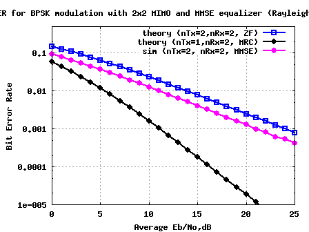
Figure: BER plot for 2×2 MIMO with MMSE equalization for BPSK in Rayleigh channel
Summary
Compared to the Zero Forcing equalizer case, at BER point, it can be seen that the Minimum Mean Square Error (MMSE) equalizer results in around 3dB of improvement. 🙂
References
[DIG-COMM-BARRY-LEE-MESSERSCHMITT] Digital Communication: Third Edition, by John R. Barry, Edward A. Lee, David G. Messerschmitt
[WIRELESS-TSE, VISWANATH] Fundamentals of Wireless Communication, David Tse, Pramod Viswanath
hii..sir m working in spatial multiplexing in mimo systems..wud u please post me the code of spatial multiplexing in rayleigh channlel..
regards
anuj
@anuj: please check the posts on https://dsplog.com/2009/04/21/six-equalizers-for-v-blast/
Hi Krishna Sankar,
The information is very helpful. I have some doubts regarding MMSE.
I am implementing MMSE & ZF with QPSK, 16-QAM and 64 QAM.
1. At higher SNR’s the BER is same for both, is it because the effect high noise will be very negligible at MMSE equalizer?
2. Even in low Snr’s the difference between MMSE and ZF is very less, in the range of 10^-4.
i am using this in combination with OFDM, does this effect the performance?
thanking you in advance
Regards
preethi
@Preethi: Are you doing MIMO with MMSE equalizer?
yes..
First of all take my gratitude for mailing such a nice demonstration and easy explanation.
I have two queries for you if you have some time please answer.
Why does MMSE provides better performance than Zero-Forcing in terms of system spectral efficiency?
Are the spatial diversity and the antenna diversity same?
Best wishes
@Zadid: Thanks.
a) By factoring in the noise power, the cross talk term gets minimized I reckon
b) By spatial one means space, and antennas are kept reasonably far apart to get spatial diversity
I need Mat Lab Code For Channel Estimation for MIMO-OFDM Systems using Recursive Least Square and MMSE or LS Algorithms…….
Please Help Me>>>>…..
I need code for “Channel Estimation for MIMO-OFDM Systems using MMSE or LS and Recursive Least Square Mehods”
Hi sir,
please let me know ,how to modify the code to get the graph for MMSE vs SNR. Thanks
@Raja: Find the difference between estimated channel and the actual channel, and average over many realizations.
Hello Sir,
I ‘m currently trying to implement a MIMO OFDM and MIMO SCFDMA with MMSE equalizer. I ‘ve read your post on OFDM in Rayleight channel where you use convolution to produce multipath. Could you give me an idea on how to do it? Like would you use the model in the MIMO script and within a loop consider subcarrier by subcarrier, then the channel would be convoluted with the transmitted symbol or multiplied? And again how would you combine together your receiver data before the equalization? Can you suggest me anything to read to understand rayleight channel with OFDMA and SCFDMA in MIMO mode and how the subcarrier are treated and equalized at the receiver?
Regards,
R.
@riccardo:
a) convolution is used to apply the multipath channel on the transmission.
b) if you are doing the modeling in frequency domain, the channel will be multiplied (assuming that the channel taps are within the cyclic prefix)
hello sir,
I am working on enhancement of high speed down link packet access in cellular network by introducing new FUS (far user streaming)scheme. I have seen your huge contribution in the area of communication. I’m facing some problem in simulation with matlab. sir can you please send me some of your matlab code for relay based cellular network
please help me sir…….!
devendra.info100@gmail.com
@Devendra: Sorry, I do not have simulation models for cellular network
Hi Krishna,
I have been working on frequency domain equalizers and i use single carrier FDE system. However when I compare the performance of Zero Forcing and MMSE equalizers they dont converge at higher SNR. I use a rayliegh random channel with 10 taps. Is this acceptable? I have also sent an email to you.
Thanks very much.
@Udesh: Please refer to the posts on equalization (zero forcing, mmse) in presence of inter symbol interference at
https://dsplog.com/tag/isi/
I also got slightly better performance for MMSE equalizer, but could see that the gap is reducing at higher SNR’s. Try increasing the SNR region to see if it converges at some point.
Hi all,
I need to implemant the spectral effeciency of MMSE receiver,
could someone help me doing this in matlab,
I hope receiving your response,
Best regards!
@Najwen: Hmm… reckon you wish to plot the spectral efficiency in bits/seconds/Hz versus Eb/N0 required to achieve say BER of 10^-5.
One way to go about this is to get the BER vs Eb/N0, dB curve for your modulation scheme with the MMSE receiver. The capacity information is theoretically computed using bit rate and bandwidth. Once you have both the data, we can plug that into the curve.
Some references:
a) Table : Bandwidth, Capacity and Eb/No requirements for symbol error rate of 10^-5
http://eetimes.com/design/communications-design/4017668/Modulation-roundup-error-rates-noise-and-capacity?pageNumber=2
b) Figure: Shannon’s capacity curve for various digital modulation schemes.
http://eetimes.com/design/communications-design/4017668/Modulation-roundup-error-rates-noise-and-capacity?pageNumber=2
c) An article on Bounds on Communication based on Shannon’s capacity
https://dsplog.com/2008/06/18/bounds-on-communication-shannon-capacity/
Hope this helps
Hi. If I would need to do a MIMO system 4×4, how could I change the inverse section? Is there an formule to calculate it as a inverse for a 2×2 matrix?
@Gidy: For 4×4 matrix inversion, you can use the inv() function in matlab or try to build your own extending the 2×2 inverse operation
http://en.wikipedia.org/wiki/Invertible_matrix#Blockwise_inversion
Hi
how about the theoretical equation for the mmse, can you give me hints as to how I should derive it or links to materials that will help?
@basco: Nice question – I have not tried digging into that. Will update if I find something.
Sir, your code of MIMO with MMSE EQUALIZER for BPSK is very helpful. But plz send me code for QPSK. I need it badly. manroopkaur588@yahoo.com
@Manroop: Extending BPSK to QPSK case is straightforward – do the detection on both the real and imaginary dimensions
Dear. Krishna Sankar.
I enjoyed your posts 🙂 thanks.
I have a doubt, I simulated your simulation by C++, but I found some different results.
With ZF, BER curve fits on your curve. but with MMSE, my BER curve performance degraded by 1 dB. Do you have some idea about this?
Thanks in advance.
Sean.
@Sean: Thanks. The MMSE 1dB delta, is it due to the noise power sigma^2 in MMSE equalization term?
i tried to simulate the code mentioned above to get the curve the output of the file is just the number 3 but no curve i’m using matlab2008rb please help me
thanx alot
@abdallah: Number3? What’s that?
Hi Krishna.
All of your articless are very helpful.
I want to know that in your code how you deceide the value of Eb/No?
Regards
Komal
@Komal: Thanks. I take typical Eb/N0 dB values from 0 to 20dB in steps of 1dB
Hello Krishna,
I have been trying to simulate 4×4 MIMO with MMSE channel estimation in LTE-Advanced in Rayleigh multichannel fading , with 16-PSK , 16-QAM, and 64-QAM modulation schemes.
Can you please help me ? I have looked at your simulation with BPSK modulation.
@Suraj: The simulations under https://dsplog.com/tag/mimo deal with the 2×2 BPSK case. Hope you should be able to extend it for the 4×4 case.
Hello sir,
Here I trying Viterbo–Boutros (VB) algorithm and the
Schnorr–Euchner (SE) algorithm.My Query is how to combine and relate with MIMO if any body know ans me…
@Shenbagaraman: Sorry, I do not know. Can you please point me to some reference
Can u tell me which ref book is useful for “Communication system with Matlab programming”
@shenbagaraman: I recall seeing this book Contemporary Communication Systems Using Matlab, Proakis, Salehi
in the past.
Hope this will be of help
Hi Krishna,
Can u provide me codes for MIMO OFDM
@Ojasvi: Sorry, I do not have MIMO+OFDM together as of now, but can point you to
a) MIMO related posts
https://dsplog.com/tag/mimo
b) OFDM related posts
https://dsplog.com/tag/ofdm
🙂
Hello. Thanks for your posts.
I have a question.
Your simulation result shows that the MMSE equalizer has 3dB improvement than the ZF equalizer.
When I simulated 2by2 MIMO system, the 4PAM-ZF system has same SER of 4PAM-MMSE system.
(Rayleigh ch./AWGN noise/SER vs SNR
But, there is a very little difference.
So, I am very confusing.
Please answer my question…
Thanks
@Ari: When you try to reduce the modulation from 4PAM to 2PAM (BPSK), are you seeing differences in the MMSE behaviour vs ZF behaviour. Further, in AWGN the difference might not be present, as there is no interference terms.
Do reply back with your findings.
Thanks for your answer. When i reduce the modulation from 4 PAM to 2 PAM, I seeing differences in the MMSE behaviour vs ZF behaviour like BPSK. Can you explain why in 4 PAM, the difference might not be present ?
@Ari: Hmm… not sure.
Hi
Should any body suggest me algorithm for bit error performance improvement using MIMO system with MMSE receiver.
@Ravi: Did you want to try an ML receiver?
https://dsplog.com/2008/12/14/mimo-ml-equalization/
Yes Mr. Krishna
I want to try ML receiver.
Pls suggest any algorithm.
Regards
@Ravi: MIMO with ML for a BPSK case discussed at
https://dsplog.com/2008/12/14/mimo-ml-equalization/
Hello Krishna,
Can you give me some idea and a sample code for implementing 16qam with ofdm. thanks
@sudarshan: I have not discussed 16QAM with OFDM, however you can find an article on BPSK with OFDM @ https://dsplog.com/2008/06/10/ofdm-bpsk-bit-error/
Further, there are quite a few 16QAM related posts @
https://dsplog.com/2007/12/09/symbol-error-rate-for-16-qam/
https://dsplog.com/2008/06/05/16qam-bit-error-gray-mapping/
Thanks Krishna for very nice and helpful posts.
I have short question; as far as I understand the simulations are for the slow fading, right?
your quick reply is greatly appreciated.
@Nikes: Each symbol gets a different channel realization. So, I guess it maps to fast fading.
Dear Krishna,
Is it possible to make face to face discussion with you regarding MIMO technology.
Regards.
RAVI
@Ravi: Am based out of Bangalore.
Hi Krishna,
How about MMSE equalization in STBC? Is it using the same code like you use in as above?
Thanks.
@kakuna: For 2 Tx, 1 Rx STBC, having ZF equalization is optimal.
Hi Khrishna,
If I want to add MMSE equalization in my MATLAB simulation for 2×2 MIMO ofdm STBC, does it the same code that you show as above?
thanks
@kakuna: You have to add OFDM and STBC to the above code.
Good work !!! The only confusing thing for me in your codes is, why in the step of “Channel and noise Noise addition”, the AWGN is in the format of 10^(-Eb_N0_dB(ii)/20)*n; while in the calculation of a,b,c,d terms, the AWGN is used as 10^(-Eb_N0_dB(ii)/10). Thanks! Jason
@Jason: For computing the MMSE equalizer, we want to use the noise power – hence 10^(-Eb_N0_dB(ii)/10)/
For adding noise, we want to use noise voltage – hence 10^(-Eb_N0_dB(ii)/20)
Helps? 🙂
Hello
I’d like to know something about MMSE. In the program, the MIMO system has MMSE at the receiving end. The coefficiets of MMSE is derived by the above formula. May I ask that ‘is the formula above for IIR MMSE’. If we use FIR MMSE, what should we modify. What is the difference between FIR and IIR MMSE?
Thank you very much
@Ann: Well, I do not know the difference between FIR and IIR MMSE.
Hi Krishna,
I am currently working on a project involving MMSE equalisation and have found your code useful. However, I am confused as to why you do the inverse of the matrix manually, would it not be easier to use simple Matlab commands to find the W matrix?
Thanks,
Tom
@Tom: I could have used the inverse using Matlab commands. However, matlab inverse does not support inverse of multidimensional matrices. Hence I chose to do the custom made one 🙂
Thanks for clarifying that for me Krishna, I am simulating 4 or 6 Tx and Tr so it would be a very long method, wouldn’t this do the same thing:
for i=1:L
W=(((H(:,:,i)).*(H(:,:,i)’))+(AWGN(i)^2.*eye(nTx))’).*(H(:,:,i)’);
end
Thanks,
Tom
@Tom: Ok
hi all
I have started MSc project in Relaying MIMO, and I have done my first code for a BPSK Signal in rayleigh fading but when try to apply it for MIMO it gives me error in matrix dimension, please see the following code and try to help me if u can, thanxxx.
% the first task is to generate a bpsk signal and simulate the BER and the second task is to convert this to MIMO
clear;clc;
N = 1e4; % Number of data bits
Nt = 1; % Number of Tx antennas
Nr = 1; % Number of Rx antennas
SNR = 0:2:20; % Signal to Noise Ratio range
x = sign (randn(Nt,N)); % BPSK data signal generation
for mm = 1:length(SNR)
Y=0;
Pe = 0;
for i = 1:10000
H = sqrt(1/2) * (randn(Nr,Nt) + j*(randn(Nr,Nt))); % Rayleigh channel
[ U L V ] = svd(H); % Singular Value Decomposition
n = sqrt(1/2)* sqrt(10^(-SNR(mm)/10)) * (randn(Nr,N) + j*(randn(Nr,N))); % Additive White Gaussian Noise, 0dB Variance
y = (L*x)+ n; % Channel and Noise addition
Y = y./L; % Equalization
Ydig = sign(real(Y));
Diff = (x – Ydig)/2;
AbsDiff = abs(Diff);
Err = sum(AbsDiff);
Pe = Pe + Err;
end
mm
Per(mm) = (Pe)/(N*10000);
end
semilogy(SNR,Per,’-b*’)
hold on
grid on
xlabel(‘SNR, dB’)
ylabel(‘Bit Error Rate’)
title(‘BER for BPSK in a Rayleigh channel’)
% The problem is when I change Nt & Nr to 4 instead of 1 the following error occur
% Error using ==> rdivide Matrix dimensions must agree. Error in ==> test1 at 16 Y = y./L; % Equalization
% What I want to do is change Nt & Nr to 4, then make sum to y so the
% matrix will be in 1 row then divide by 4 and then do error count starting from line 17
@sarmad alani: I believe an error w.r.t to matrix dimensions should be reasonably easy to fix. Hope you have already done that
Dear Krishna,
I want to implement soft input soft output MMSE equalizer for one of my projects. as inputs to the equalizer ,received symbol sequence and LLR value obtained from turbo decoding are fed. from the LLR value fed to the equalizer can generate mean and variance for symbol set(constellation). then using that mean and variance i want to find mean and variance for each symbol. (for simplicity consider BPSK and gaussian distribution of each symbol.). do u hv ay idea about how to do that. i think i hv clariffied my problem enough. Please be kind enough to reply me as am stuckd with this.
further details : Minimum mean squared error equalization using A Priori Information (Michael Tuchler , Andrew C. Singer)
@Sanka: Well, I have not studied Turbo decoder well enough to reply. Sorry.
Hi krishna
your site has been very useful to study concepts regarding ofdm and mimo. i am currently doing project related to ofdm-mimo. Can you give me some idea.. regarding how to proceed for coding 3×3 mimo or higher….
Thanks in advance.. 🙂
@prakash: Thanks.
For 3×3 or higher MIMO, the similar matrix equation holds good.
hi friends,i am doing my master thesis on LTE.i am trying to implement mmse and svd estimation but i have some probleme
this is my mmse code,could some onw help me?
i have my pdp and its length is L.
SNR = 1/(noiseVar);
beta=1;
power_delay_profile=[power_delay_profile zeros(1,fftlen-(L))];
power_delay_profile=fft(power_delay_profile);
power_delay_profile=diag(power_delay_profile(carriers));
% Calculate frequency correlation matrix
R_hh =power_delay_profile;
R_hy = R_hh + (((beta/SNR)* eye(length(carriers))));
% Calculate LMMSE estimate
h_LMMSE = (R_hh*inv(R_hy)) * h_LS;
please help!
this is the paper i refer http://www.sps.ele.tue.nl/members/C.K.Ho/paper/Robust%20MMSE%20channel%20estimation%20in%20OFDM%20systems%20with%20practical%20timing%20synchronization.pdf
@angelo: The post did not help?
For the MIMO case with MMSE detection, is the received Eb/No calibrated per transmitted stream? For example, when you go from the 1×2 case to the 2×2 case, does the noise variance stay the same, and you just add a second stream to a second antenna, of power equal to that of the original stream ? Thanks.
@Steve C: Typically, we assume that the noise variance on each receive chain is the same. However, in practice it need not me.
hello krishna sankar
do you have matlab code about soft quantization with known noise variance
(chi-square) in ofdm mobile radio system with bpsk modulation ?or any refferances or any site discuss about this?
@sam: I have not discussed the case which you have discussed above. However, I have talked about soft bit for 16QAM case @ https://dsplog.com/2009/07/05/softbit-16qam/
Hi Krishna, I wrote a matlab program to estimate x through y (y=hx+n) where n is au gaussian noise. I used MMSE to find x through the formula xHat=h’*inv(h*h’+10^(-SNR/10)*I)*y. When i wanted to compare the Theoretical SNR at the receiver (||h||^2 E(x^2)/N0) to the SNR calculated at the output of the MMSE receiver ((1/MMSE)-1), i found the SNR at the output of MMSE is much more higher than the theoretical one. Do you have any explanation on this. Does it mean that the MMSE improve the SNR ? Thank you.
@Ranou: Well, what is the gain introduced by your channel?
thanks for your your graet work
please I study for my master in frequency synchronization in mimo ofdm system but i have problem with the matlab code to simulate to find out if estimation of the CFO on one path is affected by the CFO values of the adjacent paths and examine the estimator accuracy in term of its mean and variance
please help me it’s urgent and necessary
@eng_dina: How are you modeling the CFO for MIMO systems?
If all the chains have a common RF clock, then all the chains will have similar CFO and the estimate from all the chains can be combined to improve the accuracy of the CFO estimation.
If the chains have independent RF clock, then we need to estimate CFO on each chain independently.
thanks for your your graet work
please I study for my master in frequency synchronization in mimo ofdm system but i have problem with the matlab code to simulate to find out if estimation of the CFO on one path is affected by the CFO values of the adjacent paths and examine the estimator accuracy in term of its mean and variance
sir,
do u hve MATLAB code of MIMO MCCDMA
help me please :my question is I need the matlab program calculates the’binary ‘error rate ”BER”of systems (SISO, Simo, miso mimo) COMPARISON
@bouhafs: Please have a look at
https://dsplog.com/tag/diversity/
https://dsplog.com/tag/mimo
helo krishna
actualy m working on mimo synchronization
can u help me in preamble used in mimo ofdm system ?????
how can i create a preamble in a mimo system????
@Sadaf: In a MIMO system like 802.11n, the preamble defined in 802.11a case is extended to be used in MIMO links. The SISO preamble is multiplied by a orthogonal matrix which is known at the receiver.
You may find more details about it @
https://mentor.ieee.org/802.11/file/05/11-05-1102-04-000n-joint-proposal-phy-specification.doc
would u help me , sir
i need matlab code for
Signal s—a BPSK signal that takes the values of ±1 with equal probability—passes
through channel c which has the transfer function 1 + 0.5z -1. This means that the output
of the channel at instant ݅ is equal to s(i)+0.5s(i-1). Zero-mean white Gaussian noise
v(i) with variance sigma 2 is added to the channel’s output so that
Y(i)=s(i)+0.5s(i-1)+v(i)
The sequence ݏሺ݅ሻ is white and is independent of noise v.
A three-tap linear minimum mean square error (LMMSE) equalizer is used to estimate
S(i-) using the three samples y(i), y(i-1), y(i-2) . We will solve for the two
cases of = 0 and = 1. The LMMSE equalizer forms a linear combination of
y(i), y(i-1), y(i-2) to produce the scalar estimate s^(i- ) such that ሾ[s(i-
) –- s(i- )]2 is minimized.
Find the LMMSE equalizer’s coefficients for the two cases = 0 and =1. Note
that the coefficients are a function of sigma 2. Plot the mean square error for both cases of
on the same graph using the signal-to-noise ratio (SNR) at the input of the equalizer as
the horizontal axis. SNR in this problem is defined as the ratio of signal power to sigma 2at
the input of the equalizer. (Hint: you need to obtain the signal power at the output of the
channel to obtain the power of the signal to which the noise is added.) Plot over the SNR
range from 0 dB to 12 dB.
@mohamed: I have not discussed MMSE equalization in a multipath channel till now. Thats my upcoming post.
i want a working code for 8-psk
@Maya: The code in 16PSK simulations can be easily adapted to 8PSK case
https://dsplog.com/2008/03/18/symbol-error-rate-for-16psk/
https://dsplog.com/2008/05/18/bit-error-rate-for-16psk-modulation-using-gray-mapping/
asd
Hello. Thanks for your posts.
I have a question.
Your simulation result shows that the MMSE equalizer has 3dB improvement than the ZF equalizer.
But, the reference book – [DIG-COMM-BARRY-LEE-MESSERSCHMITT] – shows MMSE detector outperforms ZF detector by 1.8dB from “10.3.9. Performance Comparison”.
Which one is correct?
When I simulated 2by2 MIMO system, the 4QAM-ZF system has same BER of BPSK-ZF system.
(Rayleigh ch./AWGN noise/BER vs SNR per bit per antenna(Eb/No)/4QAM=1/sqrt(2)*{+-1+-j})
But, there is a little difference(almost 1dB) between 4QAM-MMSE and BPSK-MMSE system.(4QAM is worse.) This shows that the MMSE outperforms ZF by 2dB at 4QAM system when the MMSE outperforms ZF by 3dB at BPSK system.
So, I am very confusing.
MMSE outperforms ZF by 2dB? 3dB?
4QAM-MMSE is worse than BPSK-MMSE?
Plz answer to me..
Thanks
@JH: The simulations which I did where comparing BPSK ZF with BPSK MMSE (and in the book, comparison is between QPSK-ZF with QPSK-MMSE). I am not sure that’s the reason for the difference in the performance.
Are you sure that QPSK MMSE is poorer than BPSK MMSE?
Hello
i need a matlab code for a zero padding in OFDM and OLA in OFDM please could you help me !!
Best regards !!
@hildaa: Sorry, I do not have the Matlab code. Good luck.
Hi,
I have a doubt:
if : W=[H’H + NoI]^-1 * H’
and if sigma_2=No/2
why do you add 10^(-Eb_N0_dB(ii)/10) constructing the hCof instead of 2* 10^(-Eb_N0_dB(ii)/10) ??? I mean, 10^(-Eb_N0_dB(ii)/10) is No/2 and in W it seems right to put No, so 2* 10^(-Eb_N0_dB(ii)/10)
The BER you can obtain with this “2*” is slightly different but my interest is mainly to correctly understand what SHOULD be there, No or No/2…
Please answer. Might be helpful
Thanks in advance
Francesco
Please answer
@Francesco: Good catch. Infact, when I coded I did not really think about it. Which plot showed better performance, with 2 or without?
Hi,
seems that we get the best performance (lower BER @ same SNR) without the 2, even if the difference is very small. Anyway this doesn’t mean that the “2” shouldn’t be there, it’s just a consideration.
But I have another question:
we know that the MMSE should come to have the same performance of the ZF for high SNRs, because the noise term become less relevant.
So, why don’t the two curves (ZF_BER and MMSE_BER) merge?
Well, actually I do have an answer for this, but my supervisor was a little reluctant to accept it:
if you plot the two curves in linear scale they do merge… but in the log scale they run as parallels… I think that’s because the reason why they merge is the SNR ( in DB!!) linearly raising… but a a linear raising of a dB value means a line in log-scale, so there won’t be a slope changing to see the curves merge in log-scale..
Also even if the receiver is different (ZF or MMSE) the system still has some properties that stay the same in the two case: I refer two the slope of the BER curve which for a Ntx=Nrx system is one decade down in 10dB (no diversity, or diversity order = 1). This must be true for both the receivers… so if they have the same slope they won’t merge in log scale.
Let me know what do you think of what I’ve said and if you have some other explanation.
Please answer
I thank you in advance anyway
Best regards
Francesco
@Franseco: My replies
1/ I rechecked the equations for MMSE. The noise term is E{n*n^H}. The variance of real and imaginary arm of noise is 0.5*10^(-Eb_N0_dB/10). When we compute the noise power, we have to add the variances of real and imaginary term and the total variance is 10^(-Eb_N0_dB/10). Agree?
2/ Well, I also have difficulty accepting the linear vs dB hypothesis. Did you try running the curve for very high values of Eb_N0_dB? Lets say till 100dB?
You dont need “2*”. What you need is noise power => sigma_2 =No/2.
OK… then this means that in the formula for W we have No/2 instead of No as it’s currently written down ?
By the way, any ideas about the curves merging thing?
Thanks a lot in advance
Francesco
@Francesco: As explained earlier
Hi,
Its a great post indeed.
I am having a very basic doubt. I am just stating the flow for my understanding:
1) Signal ‘X’ is transmitted with pilots.
2) Received signal Y = H.X + N
3) At receiver channel estimation is done i.e ‘H’ is calculated with the help ref. signals/pilots, received).
4) Then ‘W’ is calculated.
5) Now I need to retrieve the original signal (X). Can you please tell me how to do that in any case, zero forcing or MMSE. Is it just linear division or something else is involved. It will be helpful if you may tell the equation as well.
@Gaurav: Your steps are right.
In ZF, to estimate the original signal X, we need to find a matrix W which makes W*H = I.
This is a matrix division operation.
Hi,
How is the MMSE equalization done in the case of a frequency selective channel ?
(As it is not a simple multiplication, but convolution instead)
Thanks..
@KB: Yeah, the equations change. I preparing articles for the multipath channel case.
Hi Krishna Pillai
With your model the dimension of the noise correlation matrix shall be Nrx xNrx. But the dimension of the noise correlation matrix in the equalizer is Ntx x Ntx. What is the meaning of this and how can you get it in case of Nrx>Ntx?
Thanks.
@Shengyan: The noise is of dimension [Nrx x 1]. What is the noise correlation matrix which you are refering to , is it (H^H*H) ?
Hi Krishna Pillai
I think your result of the weight coefficient is not correct. could you show how did you get this result formula?
Thanks
@Shengyan: This equation is discussed in most text books. You may refer Chapter 10.3 in Digital Communication: Third Edition, by John R. Barry, Edward A. Lee, David G. Messerschmitt
This is one of the best discussion forum That I have come across. Keep it up Guys. Thanks to Krishna Pillai Garu.
@Krishna: Thanks.
Hi , how can we extend the above MIMO implementation to a general ‘n’ transmitters and ‘m’ receivers case ?
Is it possible to code for a general case or should we have separate implementations for each case (like 2×3, 3×2, 3×3, and so on..)
Also, say we have 4 transmitters and 4 receivers, how does the MMSE Equalization work in this case ?
Thanks !
@Kartik: Extending the Matlab code to an nRx x nTx case involves modification to the equalizer. In the current code, we have a 2×2 matrix inversion. If we go for higher dimension matrices, we need to change the logic for matrix inversion accordingly. Alternatively, one can use the pinv() function – but then, we loose some of the vectorizing advantages (which results in faster execution) which we now have in the code.
How Can i Calculate Noise Variance based on Received Reference and Transmitted Reference(Pilots) Symbols. Which i want to use it in MMSE Equation
Thanks & Regards,
Venki
@Venki: I am just guessing, if we know that
y = x + n, where
y is the received pilots,
x is the transmitted reference pilots,
n is the noise.
Then the variance of n can be estimated by finding E { (y-x)^2 }, where E{} is the expectation operator.
Agree?
Thanks for the previous reply………………..
If i have Reference symbols in frequency domain then can i add N0=(y-x)^2 this directly for Noise Variance Calculation……..bcz i thought noise addition should be in Time Domain……….so do i need to perform IFFT(N0) for Time domain conversion?????????????
@Venki: Noise addition in time domain. But, I think the variance does not change even if we compute in frequency domain or in time domain.
@Venki: You can do an ifft(N0) to find the noise in frequency domain. But, the variance of the noise term N0 does not change irrespective of whether we do ifft() or not. Hence doing ifft() is not needed. Agree?
Thats correct, we do not need to be in time domain. I think your solution is ok only for AWGN because otherwise you dont have channel information involved.
Another solution:
y1 <- first received reference symbol
y2 <- second received reference symbol
Then the variance of n can be estimated by finding E { (y1-y2)^2 }, where E{} is the expectation operator.
This approach is ok as long as there is not Timing offset is involed, otherwise you pilots will have phase rotation and as a results biased noise estimate.
@aydar: I agree.
can we use MMSE(apart from MRC) for SIMO?
@Chiru: But, in single input mutliple output, there is no interference term and hence I guess MRC is optimal. Agree?
Thanks for the previous reply
But, if i Use MMSE it will reduce error(Mean Square) but MRC cant reduce it…….So, how can we decide which one is suitable ………
@Chiru: MMSE reduces the error due to interference. However, if its a SIMO case, then there is no interference. Hence MRC is optimal. Agree?
a) Wont MRC have noise enhancement problem? (Because I still dont see clear difference between ZF and MRC)
b) Even if it is SIMO, in real system you will always have interference. So, my answer would be MMSE (with IRC option, where we dont estimatejust noise variance but rather noise+interferece covariance matrix).
@aydar: My replies:
a) I do not have a precise understanding of how MRC works in the case of 3 receive 2 transmit case. I am sure that having the ‘extra’ antenna at the receiver improves the diversity gain. However, am not sure what we are doing is MRC or not
b) Why do you say that there is interference in SIMO systems?
b) Well, at least in LTE we would always have an interference from other cells.
@aydar: ok
Hi
Can we user MMSE in case of SISO/SIMO?
@WirelessNewbie: Well, in the case of SISO, as there is no interference, the Zero Forcing equalization is optimal.
If SIMO case, we can use the Maximal Ratio Combining. https://dsplog.com/2008/09/28/maximal-ratio-combining/
Hi Krishna
Thanks for spending your valuable time on it
could you please refer :
http://books.google.com/books?id=3DY6OAIGu0kC&printsec=frontcover&source=gbs_v2_summary_r&cad=0#v=onepage&q=&f=false
(Introduction to Space Time Communications)
Which gives a comparison of ZF, MMSE,etc for SISO
It shows MMSE is better than ZF for SISO.
Regards
@WirelessNewbie: Sorry, the page 141 is not available from the link you provided. Let me try to get the book from the library, and I will respond.
One query: Is the claim that “ZF is better than MMSE for SISO” for a flat fading channel?
can you plz help me out to write Matlab codes about one-ring model, two-ring model, iid model, kronecker model in mimo
thanks in advance
@Hamad: Sorry, am not familiar with the one/two ring models which you are proposing.
Thanks for the previous reply
In the sample code given, the noise variance is n, but it is not used in the receiver, instead of that 10^(-Eb_N0_dB(ii)/10) is used.
Is it because the n is not known to receiver? So we have to measure the SNR in the receiver in practical case?
Thanks in advance
@WirelessNewbie: In the simulation code, n is the noise voltage signal. For MMSE equalizer, we do not need the noise voltage, rather we only need the variance of the noise. Hence the term 10^(-Eb_N0_dB(ii)/10) is used. Agree?
Yes, a practical MMSE implementation needs to know the measure the SNR at the receiver.
Hi Krishna,
I understand that MMSE is minimizing the equation
https://dsplog.com/cgi-bin/mimetex.cgi?E\left\{%20\mathbf{\left[Wy-x\right]\left[Wy-x\right]}^H\right\}
where can I find, what’s the reason for this? why we choose that equation. (I don’t even know such basics). can you suggest a book.
and in the above comment Parejas is asking you to reuse your post in his italian site(If my translation is correct). You gave him permission ? 😉
@WirelessBewbie: The derivation of the MMSE equalizer is provided in Chapter 10.3.3. of Digital Communication: Third Edition, by John R. Barry, Edward A. Lee, David G. Messerschmitt. Need to write an article about this. Another addition to the to-do list.
Btw, I have not given permission to Parejas. It seems like a spam comment.
Hola de parte de parejaspareja.es, encontre tu blog navegando por la red buscando banda ancha en google. Me parece super interesante la información que tienes en tu blog y sin lugar a dudas regresare a leerlo. Tengo una pregunta, si podria traducir tu blog “MIMO with MMSE equalizer” y añadirlos a un de mis blogs en italiano? Y por supuesto con el link direccionando a tu blog. Estare esperando tu respuesta. parejaspareja.es
what is mmse? and why we use it instead of other equaliser?
@pragya: MMSE – Minimum Mean Square Error. As you can seen from the BER curves, the BER with MMSE equalizer is lower than BER with Zero Forcing (ZF) equalizer.
Dear Krishna Pillai:
I want to combine V-BLAST and OFDM, how can I simulate this in Matlab, I know that you have not done that but can you guide me or support me for archive this goal.
On advance, thanks a lot
@Mijares: Sure, you may ask queries.
Thanks for your help, in this moment I am trying to combine Alamouti with OFDM but the BER that I got is very high, this is the code:
clear all
nFFT = 10
nDSC = 2
nBitPerSym = 2
nSym = 2
N = 4
EbN0dB = [0:35];
EsN0dB = EbN0dB + 10*log10(nDSC/nFFT) + 10*log10(10/14);
for ii = 1:length(EbN0dB)
ip = rand(1,N)>0.5
s = 2*ip-1
sCode = zeros(2,N)
sCode(:,1:2:end) = (1/sqrt(2))*reshape(s,2,N/2)
sCode(:,2:2:end) = (1/sqrt(2))*(kron(ones(1,N/2),[-1;1]).*flipud(reshape(conj(s),2,N/2)))
xF = [zeros(nSym,4) sCode(:,[1:nBitPerSym/2]) zeros(nSym,1) sCode(:,[nBitPerSym/2+1:nBitPerSym]) zeros(nSym,3)]
xt = (nFFT/sqrt(nDSC))*ifft(fftshift(xF.’)).’
xt = [xt(:,[7:10]) xt]
nTap = 10
ht = 1/sqrt(2)*1/sqrt(nTap)*(randn(nSym,nTap) + j*randn(nSym,nTap))
hF = fftshift(fft(ht,10,2))
for jj = 1:nSym
xht(jj,:) = conv(ht(jj,:),xt(jj,:))
end
xt = xht
xt = reshape(xt.’,1,nSym*(14+nTap-1))
nt = 1/sqrt(2)*[randn(1,nSym*(14+nTap-1)) + j*randn(1,nSym*(14+nTap-1))]
yt = sqrt(14/10)*xt + 10^(-EsN0dB(ii)/20)*nt;
yt = reshape(yt.’,14+nTap-1,nSym).’
yt = yt(:,[5:14])
yF = (sqrt(nDSC)/nFFT)*fftshift(fft(yt.’)).’
yF = yF./hF
yMod = yF(:,[3+[1:nBitPerSym/2] 4+[nBitPerSym/2+1:nBitPerSym] ])
ipModHat = 2*floor(real(yMod/2)) + 1
ipModHat(find(ipModHat>1)) = +1
ipModHat(find(ipModHat<-1)) = -1
ipBitHat = (ipModHat+1)/2
ipBitHat = reshape(ipBitHat.',nBitPerSym*nSym,1).'
nErr(ii) = size(find(ipBitHat – ip),2)
end
simBer = nErr/(nSym*nBitPerSym)
I hope you can help me to increase the performance of the Ber.
Regards
thanks a lot for your help, first I want to combine Alamouti with OFDM, but the problem is that I get a very high BER, this is the code:
clear all
nFFT = 10
nDSC = 2
nBitPerSym = 2
nSym = 2
N = 4
EbN0dB = [0:35];
EsN0dB = EbN0dB + 10*log10(nDSC/nFFT) + 10*log10(10/14);
for ii = 1:length(EbN0dB)
ip = rand(1,N)>0.5
s = 2*ip-1
sCode = zeros(2,N)
sCode(:,1:2:end) = (1/sqrt(2))*reshape(s,2,N/2)
sCode(:,2:2:end) = (1/sqrt(2))*(kron(ones(1,N/2),[-1;1]).*flipud(reshape(conj(s),2,N/2)))
xF = [zeros(nSym,4) sCode(:,[1:nBitPerSym/2]) zeros(nSym,1) sCode(:,[nBitPerSym/2+1:nBitPerSym]) zeros(nSym,3)]
xt = (nFFT/sqrt(nDSC))*ifft(fftshift(xF.’)).’
xt = [xt(:,[7:10]) xt]
nTap = 10
ht = 1/sqrt(2)*1/sqrt(nTap)*(randn(nSym,nTap) + j*randn(nSym,nTap))
hF = fftshift(fft(ht,10,2))
for jj = 1:nSym
xht(jj,:) = conv(ht(jj,:),xt(jj,:))
end
xt = xht
xt = reshape(xt.’,1,nSym*(14+nTap-1))
nt = 1/sqrt(2)*[randn(1,nSym*(14+nTap-1)) + j*randn(1,nSym*(14+nTap-1))]
yt = sqrt(14/10)*xt + 10^(-EsN0dB(ii)/20)*nt;
yt = reshape(yt.’,14+nTap-1,nSym).’
yt = yt(:,[5:14])
yF = (sqrt(nDSC)/nFFT)*fftshift(fft(yt.’)).’
yF = yF./hF
yMod = yF(:,[3+[1:nBitPerSym/2] 4+[nBitPerSym/2+1:nBitPerSym] ])
ipModHat = 2*floor(real(yMod/2)) + 1
ipModHat(find(ipModHat>1)) = +1
ipModHat(find(ipModHat<-1)) = -1
ipBitHat = (ipModHat+1)/2
ipBitHat = reshape(ipBitHat.',nBitPerSym*nSym,1).'
nErr(ii) = size(find(ipBitHat – ip),2)
end
simBer = nErr/(nSym*nBitPerSym)
I hope you can help me for increase the performance of the BER
Thanks for all
Regards
Hello,
Have you received help??
Thanks.
@ Mijares: Sorry, due to time constraints, I typically do not debug the code. If you have explicit queries, I can try to answer.
DEAR sir…i m pragya and i hav heard about u a lot.
i m in final yr so i hav 2 mak a projct and my projct is MIMO WID MMSE EQUALISER..
so if possible plzz guide me as i hav no knowledge regarding dis..
plzzzzzzzzzzzzzzz
my ID z pragyamitra@gmail.com
i am waitin 4 ur respnse desperatly…
@pragya: I hope this post serves as a good introduction. If you have additional queries, plz revert.
I am studying about MIMO Tomlinson Harashima Precoding. Do you have any document or program relate to MIMO THP?
@dungpt: Sorry, am not faimiliar with MIMO Tomlinson Harashima Precoding
thnx for ur response sir..i think em confusing everything 🙁 i have juz strted doen work on it,can u plzz guide me what is da difference between diversity and beamforming???
@maya: Well, I diversity in the general sense means – the using the extra information which is available and/or transmitted to improve the reliability of the communication link. In general, if we have multiple antennas at the receiver, we have to think of intelligent ways to do receive diversity. Similarly, if we have multiple transmit antennas, we have to figure out ways of processing of the data such that the reliability of the link is increased.
Beamforming is one way of doing transmit diversity, where the knowledge of the channel is used to process the information at the transmitter.
Hope this helps.
hey sir,can u plzz telme dat how we can find theoretical ber for mimo systems???
and also can u guide me dat can we send a copy of data from 2 transmitters at da same tym instead of selecting a pair of data n den sending it,,is it a right approach???
@maya: Well, from the simulations which I did a 2 transmit 2 receive MIMO V-BLAST system with Zero Forcing Equalizer in flat fading rayleigh channel, performed about identically with a 1 transmit 1 receive system.
Well, if we send the same information from two transmit antennas, I believe there is not much performance gain in flat fading rayleigh channel. I have written a brief post on transmit beamforming, which briefly touches upon this topic
https://dsplog.com/2009/04/13/transmit-beamforming/
Hope this helps.
im actuallt trying to do channel estimation using mmse for 2 tx 1 rx but having trouble understanding it…please help
@safwan: Well, I do not quite understand the need for having an MMSE equalizer for a 2 transmit 1 receive system. If there is no coding at the transmitter, then 2 transmit 1 receive system performs as if its a 1 transmit 1 receive system. Agree?
well,im actually implementing MIMO-OFDM on the 2 tx and 1 rx…i want to get the most optimum training sequence and then estimate the channel using mmse
@safwan: For chnnel training, you may use ideas suggested in 802.11n spec. Transmitting from both the antenna with a multiplication by an orthogonal matrix. You can have a look at the old version of 802.11n spec @
https://mentor.ieee.org/802.11/dcn/05/11-05-1102-03-000n-joint-proposal-phy-specification.doc
Or you could use CAZAC sequences with cyclic shift between MIMO users as it is in LTE uplink.
@aydar: What are CAZAC sequences? Can you please write more about it.
“…The CAZAC sequence is a sequence that has constant amplitude in both regions of time and frequency and it has always Zero Auto-Correlation for time shift that is other than the cyclic self-correlation value is 0. As the CAZAC sequence has Constant amplitude in a time region, it can keep PAPR (Peak to Average Power Ratio) low. As the CAZAC sequence also has Constant amplitude in a frequency region, it is a sequence suitable for propagation path estimation in the frequency region. Here, a small PAPR means that it can keep the power consumption low. This feature is preferred in the mobile communication. …”
Pilots for LTE specified in 3GPP 36.211.
@aydar: Thanks.
Helleo sir
I am doing project on Bit Error performance of MIMO system. Pls send me comparative BER analysis of MIMO system for different modulation technique such as BPSK QPSK and QAM. This information is very useful for me. Pls send it for me.
Regards.
RAVI
@Ravi: Hope you will be able to use the posts on MIMO and the posts on symbol error rate for M-QAM in OFDM to get what you need.
http://www.dsplog.com/tag/mimo
https://dsplog.com/2012/01/01/symbol-error-rate-16qam-64qam-256qam/
Hello,
how do you actually implement mmse for a 2 tx 1 rx system?having a bit of trouble undestanding it for these settings
@safwan: But, why would you want an MMSE for a 2 transmit, 1 receive system?
How we can calculate bit error rate.
@Alvina: Well, count the number of differences between received bits and transmitted bits and divide that by total number of transmitted bits … 🙂
Thanks Krishna alots! I have question about your programme. When you compute the inverse of (conj(H)*H) matrix you use:
hCof(1,1,:) = sum(h(:,2,:).*conj(h(:,2,:)),1);
hCof(2,2,:) = sum(h(:,1,:).*conj(h(:,1,:)),1);
hCof(2,1,:) = -sum(h(:,2,:).*conj(h(:,1,:)),1);
hCof(1,2,:) = -sum(h(:,1,:).*conj(h(:,2,:)),1);
whereas the product between two matrices is:
hCof(1,1,:) = sum(h(2,:,:).*conj(h(:,2,:)),1);
hCof(2,2,:) = sum(h(1,:,:).*conj(h(:,1,:)),1);
hCof(2,1,:) = -sum(h(2,:,:).*conj(h(:,1,:)),1);
hCof(1,2,:) = -sum(h(1,:,:).*conj(h(:,2,:)),1);
when I apply these changes I do not find the same results.
best regards
@Wassim: Note that am computing the cofactor of the matrix (H^H*H). Inverse of a [2 x 2] matrix
[a b; c d] = 1/(ad-bc)[d -b;-c a]
The code which you have pasted does not include the matrix rearrangement to compute the cofactor. Agree?
very good
Sir,
Can you just give me your email address, so that I can mail you my queries. I am working on MIMO OFDM equalization techniques and have a series of questions that I have doubts in. Will you please kindly send your address at cvvarun_raj@yahoo.co.in?
Thanking You
Regards
Varun
@ Varun Raj: you may find my email address in the page
https://dsplog.com/contact-us/
Further, you may find many articles discussion receiver structures for MIMO @ https://dsplog.com/tag/mimo.
Why don’t use the same channel (h) for a Eb_N0? I use the following code, Is it well, not??
clear
N = 60000; % number of bits or symbols
Eb_N0_dB = [0:20]; % multiple Eb/N0 values
nTx = 2;
nRx = 2;
for ii = 1:length(Eb_N0_dB)
N0 = 10.^(-Eb_N0_dB./10);
criterio =’mmse’;
esquema = ‘psk’;
M = 2;
fuente = load(‘simTx_120000_2′);
fuenteselec = fuente.x;
fuentedecimal(1,:) = fuenteselec(1,1:60000); % transmito según el estudio de convergencia 60000 símbolos para un error del 1%
bitsTx = length(fuentedecimal) * log2(M);
fuentebinario = decimal_bin (fuentedecimal,M);
fuenteDemux = demux(fuentedecimal,nTx);
%Modulo los datos a transmitir (cada antena tx 1024 símbolos).
sMod = modulador(fuenteDemux,esquema,M,1);
H = 1/sqrt(2)*[randn(nRx,nTx) + j*randn(nRx,nTx)]; % Rayleigh channel
n = sqrt(N0(ii)/2)*(randn(nRx,N/nTx) + j*randn(nRx,N/nTx)); % white gaussian noise, 0dB variance
% Channel and noise Noise addition
y = H*sMod + n; % Dividimos por 20 porque así nos ahorramos hacer la raiz.
% Receiver
% Forming the MMSE equalization matrix W = inv(H^H*H+sigma^2*I)*H^H
% H^H*H is of dimension [nTx x nTx]. In this case [2 x 2]
% Inverse of a [2×2] matrix [a b; c d] = 1/(ad-bc)[d -b;-c a]
G = inv(H’*H + N0(ii)*eye(nTx))*H’;
yMod = G*y; % H^H * y
[Y,Es_rx] = demodulador(yMod,esquema,M);
datosmux = mux(Y);
Datosbinarios = decimal_bin (datosmux,M);
if length(fuentebinario) ~= length(Datosbinarios)
Datosbinarios = Datosbinarios(1,1:length(fuentebinario));
end
nErr(ii) = sum(fuentebinario~=Datosbinarios);
% sMod = reshape(yMod,[1,N]);
%
% % receiver – hard decision decoding
% ipHat = real(sMod)>0;
%
% % counting the errors
% nErr(ii) = size(find([ip- ipHat]),2);
end
simBer = nErr/N; % simulated ber
EbN0Lin = 10.^(Eb_N0_dB/10);
theoryBer_nRx1 = 0.5.*(1-1*(1+1./EbN0Lin).^(-0.5));
p = 1/2 – 1/2*(1+1./EbN0Lin).^(-1/2);
theoryBerMRC_nRx2 = p.^2.*(1+2*(1-p));
close all
figure
semilogy(Eb_N0_dB,theoryBer_nRx1,’bp-‘,’LineWidth’,2);
hold on
semilogy(Eb_N0_dB,theoryBerMRC_nRx2,’kd-‘,’LineWidth’,2);
semilogy(Eb_N0_dB,simBer,’mo-‘,’LineWidth’,2);
axis([0 25 10^-5 0.5])
grid on
legend(‘theory (nTx=2,nRx=2, ZF)’, ‘theory (nTx=1,nRx=2, MRC)’, ‘sim (nTx=2, nRx=2, MMSE)’);
xlabel(‘Average Eb/No,dB’);
ylabel(‘Bit Error Rate’);
title(‘BER for BPSK modulation with 2×2 MIMO and MMSE equalizer (Rayleigh channel)’);
@MIMO: Well, I did not understand your question.
hello,
i’m see your script of MIMO equalizer MMSE for 2×2 and my doubt is, why don’t you multiply for 2 the noise? because you consider Es = 1 (ok) but there is 2 antennas. It would want so (10^(-Eb_N0_dB(ii)/20)*2), not?
@mimo: Well, recall that we have two receive chains, and the term 10^(-Eb_N0_dB(ii)/20) is applied for both.
Makes sense?
Dear sir,
I have utilized the MMSE equalizer defined by equation 1./(h.*conj(h)+ 10^(-Eb_N0_dB/10)).*conj(h) for frequency domain equalization of a single carrier modulation system. Now i have to give the reference of this equation in my research work. So kindly tell me the book or any paper which includes so that i could refer this. Plz also provide a soft copy (pdf, web link) if available.
I am working on developing IQ Imabalance compensation scheme in MIMO-OFDM systems. I have done IQ Compensation in OFDM systems but when I am combining MIMO with OFDM, I am not getting proper BER curve and the results r too bad, I have used rayleigh channel and added AWGN noise to the signal transmitted and assumed that the channel is flat, known and the path gains doesnt change for two OFDM symbol durations.I have used Alamouti STC for 2X2 MIMO channel. Please help me getting a solution and send me some related MATLAB codes
@NAVAL: It’s bit hard to say, why the code which is working for 1×1 OFDM is not working for 2×2 OFDM. I think to nail the problem, you should remove awgn, channel etc and make sure that your algorithm is working in ideal conditions. Btw, it sounds like you are trying to do receive I/Q imbalance estimation/compensation? Why do you need the ‘channel is constant for two symbol duration’ assumption.
sir pls can any one send me the matlab code for space frequency coded bs-cdme for broadband mobile comm(2X2 MIMO)
@pradhyu: Sorry, I have not worked on space frequency coding.
Hi Mr. Krishna,
Do you think that the performance would change in a 4QAM scheme? I have simulated and it is slightly worse but it does not make sense to me…
thanks
@neon: I think, symbol error rate performance with 2×2 4-QAM should be slightly better than symbol error rate performance of 1×1 4 QAM case.
Agree?
Hi,
I agree that it should be slightly better than 1×1 case. What I meant was the comparison between bpsk case and 4 qam case. for zero forcing and 2×2 mimo system both bpsk and 4qam achieve the same performance, but for the mmse case 4qam is slightly worse than bpsk, i suppose it comes from the fact that 4qam is more affected by the noise. Am I right?
thanks Mr. Krishna
@neon: What was your comparison metric – bit error rate or symbol error rate? Were you using Eb/No or Es/No?
Hi,
I was using Eb/No.
Thanks
Hi
I was using Eb/No and BER,
Thanks
cher monsieur
J’essaye de simuler un système SC-FDMA qui est proche du OFDM.
Donc j’ai transmet mes symboles sur un canal de Rayleigh que j’ai modalisé par la fonction suivante:
T(i)=sqrt(2).*(xtr(i)*(t(i)-ret(i))).*exp(2*pi*j*(fc+wn(i))*t(i)).*exp(-j*2*pi*fc*d/c);
Avec T(i) les symboles recus et xtr(i) les symboles émis et ret(i) et le retard de propagation.
Ensuite j’ai ajouté un bruit gaussien:
Eb=G*G’;
RSB=10;
N0=Eb/(10^(RSB/10));
b=sqrt(N0/2)*randn(1,length(T));
je recoit alors
W=T+b;
le problème maintenant que lorsque je veux égalisé avec un mmse..c’est que je suis incapable de déduire la fonction de transfert du canal h…aidez moi s’il vous plait!!
thinks
Em dang can tim file mo phong he thong MIMO-OFDM bang matlab de thay ro tac dung cua phan tap duoc ung dung trong he thong nay.
@quynhchi: Can you please translate that query into english.
Perhaps the title could be spesify because there are several MIMO mode (STBC/STC, BLAST-family,SM, STTC).
If I’m not mistaken, MIMO that your refer in this article is SM Mode (usually using V-Blast).
So, I think the title sould be “Spatial Mutliplex MIMO…” or “V-BLAST MIMO…”
thx
@andjas: Yes, the post describes spatial multiplexing (aka V-BLAST). I would prefer keeping the title as I think V-BLAST is the simplest form of MIMO (atleast to explain) when compared to STBC etc.
Ok Mr. Krishna, that’s your right because what you said is true.
Mr. Krishna, I’ve been making correlated and uncorrelated MIMO channel model based on WiMAX Forum Channel Model Recommendation and ITU Channel Model recommendation. As I know, channel model doesn’t have parameters that can be directly analyst, is our channel model correct or not.
1. Could you give me some advice/ material about steps/process to make MIMO Channel?
2. Could you explain how to analyst correctness of my MIMO channel model?
3. Could you send me example/script of MIMO channel model (correlated/ uncorrelated)? So, I can compare my model with yours.
Thank you, A.W.
@andjas: My replies:
1. One great reference is the channel model defined by the High Throughput study group for 802.11n standards development.
Tgn Channel Models, Vinko Erceg et al. The document provides a good overview of MIMO channel modeling – includng the effect of antenna correlation (based on antenna spacing). effect of fluorescent lights, doppler for different indoor multipath characteristics.
(2). (3). The Matlab source code for TGN channel models is available in public domain. You may check @
L. Schumacher “WLAN MIMO Channel Matlab program,” download information: http://www.info.fundp.ac.be/~lsc/Research/IEEE_80211_HTSG_CMSC/distribution_terms.html
I think, those models should be a good point to start.
Most of my models are simple flat fading un-correlated rayleigh channel. Hence, might not be of much help to you.
Hope this helps.
Thanks a lot Mr.Krishna.
hai sir ,
plz send the COSTBC matlab code for MIMO channels
hai sir,
please send QOSTBC for MIMO channels based on freqency flat rayleigh fading channels…
@Murali: I have not worked on QOSTBC
For BPSK modulation in flat Rayleigh channel, you may look up @
https://dsplog.com/2008/08/10/ber-bpsk-rayleigh-channel/
For QPSK in AWGN, you may look up @
https://dsplog.com/2007/11/06/symbol-error-rate-for-4-qam/
Hope this helps.
Hi Krishna,
I wanted to know how the equalization parameter look like if Eqz is done in the frequency domain for MMSE. (the scenario thought of here is for equalizing after DFT in an OFDM chain).
TIA,
Best Regards,
Gavigod
@gavigod: Hmm… even for OFDM, the equalzation parameters will look similiar (as long as the channel is assumed to be flat fading – which is reasonable in OFDM).
Do you agree?
yes. it is, thanks krishna.
oke, Mr. thanks for you advice.. nice to know you..
Hi mr.khrisna can you help me about mmse detector on cdma receiver?? it’s same matlab script with MMSE Equalizer??
thanks
@jaka: For CDMA, the concept remains the same. However, I would think that to simulate the CDMA MMSE detector case, the Matlab script in this post need to be modified to include:
(a) spreading and depreading,
(b) make flat fading rayleigh channel to a frequency selective channel
(c) remove mimo and make it a single spatial stream.
Hola Krishna,
gracias por este blog, estoy interesada en procesado de señal para MIMO. Hasta ahora yo me he centrado en banda estrecha utilizando vblast, qostbc… pero quiero entrar en banda ancha y no se que algoritmo utilizar para evitar la ISI. Tienes algún algoritmo implementado en Matlab que me pueda servir de base para yo empezar en banda ancha?
Muchas gracias.
@MIMO: Can you please translate your query to english
OK thank you very much 😀
hi? sir,
when i simulated MMSE 16QAM 2×2 sysem
it’s performance almost same as zero-forcing
is it a right? i used below equation
inv(H^H*H+10^(-SNR/10)*Im)*H^H*R;
(Im:identity matrix, H:channel, R:received
signal inv:inverse)
is it depend on noise variance?
please answer me thanks
@dokich: From the analysis done on BPSK modulation, the MMSE equalier should provide slightly better performance that ZF equalizer (for any value of noise variance). So, there might be some bug in your simulation setup.
Try forcing the noise variance term in the MMSE equalizer to be zero. Then you should get the identical performance to ZF equalizer. Once you obtain that, you may try with different values of noise variance.
Hope this helps.
thank you for your answer,
i try to your advice but it still worse than ZF equalizer.
this is my code
H = (randn(N,M) +sqrt(-1) * randn(N,M)) / sqrt(2)
sigma2 = 0.5 / (10^(SNR/10))
noise = sqrt(sigma2) * (randn(N, 1) + sqrt(-1) * randn(N, 1))
for(a=1:no_data)
u=[]; %Tx data
for s = 1:M
u=[u;data(s,a)];
end
m=M;
n=N;
m=2*m;
n=2*n;
r=H*u+noise(:,a);
rmm = [real(r);imag(r)];
umm = [real(u);imag(u)];
Hmm = [[real(H),-imag(H)];[imag(H),real(H)]];
Im=eye(m,m);
ummHat=inv(Hmm’*Hmm+10^(-SNR/10)*Im)*Hmm’*rmm;
[row col]=size(ummHat);
for(j=1:row)
for(k=1:col)
if ummHat(j,k)<-2 ummHat(j,k)=-3;
elseif ummHat(j,k)<0 ummHat(j,k)=-1;
elseif ummHat(j,k)<2 ummHat(j,k)=1;
else ummHat(j,k)=3;
end
end
end
if sum(norm(ummHat-umm)^2)~=0
error_MMSE=error_MMSE+1;
end
end%end of no_data MMSE
if you have a time please help me to find problem sorry to border you thanks
@dokich: From a quick look, your equalizer equation seems correct. Do not know whether there are hidden bugs.
Did you want to try with modifying the Matlab code which I have provided in the post.
What is the “NoI” means and why it is equal to 10^(-snr_dB(i)/10)
thanks alot
@John: N0 is the noise variance and its multiplied by an identity matrix I (to ensure that matrix algebra holds good). Since N0 is the noise variance, we define it as 10^(-Eb_N0_dB(ii)/10)
Hope this helps.
hai sir can i get the codings related soft parallel interference cancellation algorithm (SPIC) for MIMO OFDM for the Spatial Multiplexing Interference(SMI)
@Raaghavan: I have written posts on successive interference cancellation
URI: https://dsplog.com/tag/sic/
Hope this helps.
Thank you sir
Hi Kirshna
Can u please give some stuff on MMSE equalization or can u explain the method u used for equalization.
yHat_mmse = 1./(h.*conj(h)+ 10^(-Eb_N0_dB/10)).*conj(h).*y; % mmse equalization
Thanks
@Abrar: When equalizing by H^H matrix, we are considering the noise variance too. If the noise is high, the noise will be the dominating component.
this is the case of MIMO with MMSE equalizer.but if we want to use it in the OFDM and “not” in MIMO ofdm, then what would the matlab code be?can you kindly help me on this?
@shahid: The same concepts hold good. However, for the SISO OFDM case, I do not see the need for using a MMSE equalizer. A simple ZF equalizer should suffice. I have written a post on BPSK over OFDM in a Rayleigh multipath channel
URI: https://dsplog.com/2008/08/26/ofdm-rayleigh-channel-ber-bpsk/
Hope this helps.
hello krishna
i want to simulate a MC-CDMA system that in it calculate PAPR and detect diffrent users with BER calculating and can not do this completly. for this i ask you that if have no problem for you help and give me a matlab file about this problem
thanks a lot for your attention
@hossein: Sorry, I do not have a Matlab code which explicitly does this. For PAPR, you may refer to the posts
with the URI: https://dsplog.com/tag/papr/
Since MC-CDMA can be built upon OFDM simulations, you may refer to the posts with the URI: https://dsplog.com/tag/ofdm/
Hope this helps.
Yeah they provide the same performance .. ZF is indeed optimal when it comes to SISO systems 🙂
@Shefo666: And for completeness, I thought of adding ML decoding also into the code snippet. You can see that the error in SISO Rayleigh channel for ZF, MMSE, ML are the same.
% ml decoding
ipHat_ml = abs(y – h.*1) < abs(y+h.*1); % counting the errors nErr_ml = size(find([ip- ipHat_ml]),2)
Yeah its very helpful .. thanks for the clarification
@Shefo666: I think the ZF equalizer is optimal in SISO systems.
With a simple Matlab/Octave script may I try to show that ZF and MMSE equalizer gives the same BER. Infact, am not sure whether we can call it as ZF/MMSE equalization – as there is no interference terms.
% Matlab/Octave code snippet for comparing zero forcing and MMSE equalization for SISI
clear
N = 10^4 % number of bits or symbols
ip = rand(1,N)>0.5; % generating 0,1 with equal probability
s = 2*ip-1; % BPSK modulation 0 -> -1;
Eb_N0_dB = 3;
n = 1/sqrt(2)*[randn(1,N) + j*randn(1,N)]; % white gaussian noise, 0dB variance
h = 1/sqrt(2)*[randn(1,N) + j*randn(1,N)]; % Rayleigh channel
% Channel and noise Noise addition
y = h.*s + 10^(-Eb_N0_dB/20)*n;
% equalization
yHat_zf = y./h; % zf equalization
yHat_mmse = 1./(h.*conj(h)+ 10^(-Eb_N0_dB/10)).*conj(h).*y; % mmse equalization
% receiver – hard decision decoding
ipHat_zf = real(yHat_zf)>0;
ipHat_mmse = real(yHat_mmse)>0;
% counting the errors
nErr_zf = size(find([ip- ipHat_zf]),2)
nErr_mmse = size(find([ip- ipHat_mmse]),2)
Can see that nErr_zf and nErr_mmse is the same. Hope this helps.
Dear Krishna Pillai,
Thanks for the very interesting blog ..
I am wondering whether it makes any sense to apply MMSE and ML equalization on SISO communication systems in order to get over the ZF equalization major problem of noise enhancement (when channel is in deep fade).
In such a case, how is the theoretical BER performance of BPSK (for instance) over flat rayleigh (given by proakis, Digital communications) affected ? can u reccommend any papers that calculate the theoretical BER performance of ML and MMSE equalization over flat fading .. Most papers i got assume ZF equalization when it comes to SISO systems !
@mehrkhan: The presence of a 3-tap channel does not imply that channel varies with time – it just means that channel varies across frequency.
There can be channel conditions (for eg indoor), where it can be reasonably assumed that the channel remains constant over two symbol periods.
in addition to my first request for investigating the MIMO-OFDM system one question is that how can we maintain the channel coefficients equal for two consecutive symbol(for satisfying the Alamouti decoding scheme) while we are modulating symbols on for example 64 subcarriers of one antenna and the channel has 3-taps?
@nano686: Were you referring to large MIMO system where the channel dimension is large such that the simple matrix inversion approaches becomes impractical?
Sure, we can discuss. Please email the details.
sir
do you know how to find channel coefficients using expectation and maximization algorithm for mimo cdma model.if so please explain through matlab
@phaneendra: sorry, am not familiar.
@mehrkhan: With Alamouti coding, since the channel H^H*H is a diagonal, I do not think there is advantage by using MMSE equalization. Anyhow will check and let know.
Dear Mr Krishna
I am working on localization technique in MIMO cellular system and i need you advice which is better to select parameter GA or PSO
Regards
Fadil
@Fadil: Sorry, I do not know about the topic
Thanks Krishna alots! Try to research MIMO, I also have a project with MIMO system: Using Genetic Alogrithms as a tool to handle large numbers of users. I hope we can discuss this project if you don’t mind.
Regards!
Hi & Thanks for your good posts
will you combine the concepts that you have investigated so far step by step and show how is the performance of
MIMO-OFDM systems with alamouti coding and different equalizers such as MMSE in multi-tap Rayligh channel as your conclusion and complex of all of these concepts.