I have written another article in DSPDesginLine.com. This article can be treated as the third post in the series aimed at understanding Shannon’s capacity equation.
For the first two posts in the series are:
1. Understanding Shannon’s capacity equation
2. Bounds on Communication based on Shannon’s capacity
The article summarizes the symbol error rate derivations in AWGN for modulation schemes like BPSK, QPSK, 4PAM, 16QAM, 16PSK, 64QAM and 32PSK.
The article in DSPDesignline.com details the following:
- Based on the knowledge of bandwidth requirements for each type of modulation scheme, the capacity in bits/seconds/Hz is listed.
- Using the knowledge that the symbol to noise ratio
is
times the bit to noise ratio
, the symbol error rate vs
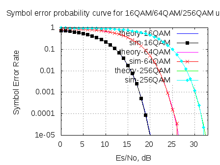
curves are plotted.
- Using symbol error rate versus
plots, the
required for achieving symbol error rate of
is identified.
- Upon having the capacity and
requirement, the requirements for BPSK, QPSK, 4PAM, 16QAM, 16PSK, 64QAM and 32PSK are mapped on to the Shannon’s capacity vs Eb/No curve.
- Assuming Gray coded modulation mapping, each symbol error causes one bit out of
bits to be in error. So, the relation between symbol error and bit error is,
.
- Using this assumption, the Bit Error Rate (BER) for BPSK, QPSK, 4PAM, 16QAM, 16PSK, 64QAM and 32PSK are listed and the BER vs Eb/No curve plotted.
Hope this article serves as a nice overview of the various digital modulation schemes. Click here to read the full article in DSPDesignline.com
Hi Krishna,
Can you give me a link to a MATLAB pgm which would help us estimate the IQ imbalance in the received OFDM signal.?
@Bala: Sorry, do not have it.
Hi there,
This looks like a really good article in DSPDesignLine, except that now it redirects to eetimes.com and although the text of the article is there, all the image links seem to be broken. Without the images containing the formulas, the article is now useless. Is there any way you can fix it?
@Jeffrey Bridge: Thanks for pointing that out. Let me ping eetimes.com to get the article fixed
Hi Krishna,
Given that the modulation type is either 16QAm or 16APSK, is there a formula to relate the SNR(Es/No) to the average constellation dispersion for each modulation type? How do we derive the relationship?
Thanks.
@Donny: for a given Es/N0, i recall 16-QAM gives lower symbol error rate that 16-PSK.
One can find a relationship between them by computing the ratio of the distance between the constellation points in each case.
Please use the link below to get more information on the comparison of 16PSK vs 16QAM
https://dsplog.com/2008/03/29/comparing-16psk-vs-16qam-for-symbol-error-rate/
Hare Krishna ! 🙂
Thanks a lot for all the information you posted here, it was very useful for me.
hi can you please help me with matlab code for area spectral efficiency in OFDMA or LTE. thanks
@Junaid: are you trying to plot the bits per second per Hz for the different modulation schemes?
You can take a look at
https://dsplog.com/2008/06/18/bounds-on-communication-shannon-capacity/
http://eetimes.com/design/communications-design/4017668/Modulation-roundup-error-rates-noise-and-capacity?pageNumber=1
will anybody help me to implement SLM technique of PAPR reduction in matlab?
please do needfull if any one.
Hi Krishna,
Have you any work on 2×2 MIMO OFDM systems with rayleigh channel, for BPSK, QPSK, 8PSK and 16PSK?
Much appreciated
@Adam Scott: There are articles on MIMO discussed at https://dsplog.com/tag/mimo
But most of there are discussing using BPSK modulation as example. Extending this to higher order modulation seems reasonably straightforward though
Hi,
I just need some help relating to data rate and bandwidth. I have a fixed bandwidth of transmission of 25KHz. So i want to calculate the data rates in different types of modulation to determine which one i can use. Can you help me with some formula with which i could calculate this.. Or any other better approach?
Thanks a lot
@Ratheesh: Hope the post on capacity may be of help to you
https://dsplog.com/2008/06/18/bounds-on-communication-shannon-capacity/
http://eetimes.com/design/communications-design/4017668/Modulation-roundup-error-rates-noise-and-capacity?pageNumber=1
sir i have to prepare a model and project on the comparison between BPSK and QPSK. can you please help me in making the model..or you can provide any information regarding this topic.
@akash: You can refer to the posts on
a) BPSK BER
https://dsplog.com/2007/08/05/bit-error-probability-for-bpsk-modulation
b) QPSK symbol error rate
https://dsplog.com/2007/11/06/symbol-error-rate-for-4-qam/
sir, i am looking for QPSK Algorithms…
can you provide some details about few algorithms
@radhakrishna: Hope the post on QPSK symbol error rate helps
https://dsplog.com/2007/11/06/symbol-error-rate-for-4-qam/
i want the code for 8-qam.plese provide it to me
@lavanya: Am hoping that you will be able to develop the 8QAM symbol error rate code using the 16QAM case as reference.
https://dsplog.com/2007/12/09/symbol-error-rate-for-16-qam/
https://dsplog.com/2008/06/05/16qam-bit-error-gray-mapping/
I need mapping and demapping function commands in MATLAB code for OFDMA and SC-FDMA. will you please help me.
@Shareef: Is it modulation and demodulation mapping i.e. bits to constellation?
please i need it too : you very kind man 🙂
@risky: emailed you the instructions
I would like to share in this web bcz it very use full
hi krishna
do u have a matlab simulation for 64 QAM that first generates random binary bits then map them to symbols instead of generating symbols directly ??
https://dsplog.com/db-install/wp-content/uploads/2008/04/script_m_qam_ser.m
i have this code but it generates the symbols directly
thx in advance
@Abd: You can find a post on 16QAM BER with Grey coding
https://dsplog.com/2008/06/05/16qam-bit-error-gray-mapping/#Simulation%20Model
In that post, bits are generated and then converted to symbols.
Dear Krishna,
I just want to first thank you for your posts especially us students from un developed countries. Your website has taught us a lot and we do not feel inferior.
I was so bad at scripts but i picket interest and your work has greatly helped me. Thank you so much and May God bless you.
I want to kindly ask you for the matlab/ octave script for simulating BER vs SNR per bit (Eb/No) for various digital modulation schemes(Comparing BPSK, QPSK, 4PAM, 16QAM, 16PSK, 64QAM and 32PSK).
I was able to see your output from this website “http://www.eetimes.com/design/signal-processing-dsp/4017668/Modulation-roundup-error-rates-noise-and-capacity?pageNumber=2” but i can not access the script.
I also want to ask you if you have examples of matlab/octave scripts for Sum capacity Vs SNR of MIMO or MU-MIMO with correlated and uncorrelated channel to help with some of them.
Otherwise am waiting to hear from you. Thank you
I can not say enough thank you for your posts on https://dsplog.com. If i were to give you a gift it would be ” to give you the ability to see yourself as others see you, then you could really see how special you are and how you have made a big difference in lives of many people”
@rachael: Thanks for the kind words. Will add a post on sum capacity soon
i face a problem of BER formula for math lab simulation which is
BER=.5 erfc[sqrt(snr)/2]
i need to analyze the performance of a short distance terrestrial OWC system as a function of wavelength.
i need a help that BER formula is right or wrong.
@maruf: what is the modulation which is being used?
hi krishna …..
hi sir …
Can you help me about tutorials from the m-QAM (m = 4,8,16,32,64),
about the theory, the calculation of bit error probability (BER) and the constellation of m-QAM..
thanks before……
@wep: The following posts might be of help
https://dsplog.com/2007/12/09/symbol-error-rate-for-16-qam/
https://dsplog.com/2008/06/05/16qam-bit-error-gray-mapping/
https://dsplog.com/2008/05/24/article-in-dspdesignlinecom-m-qam-symbol-error/
Sir,
can u give me the matlab code for the BER compersion of conventional BPSK, QPSK and 8PSK over an AWGN channel.
Regards
@Stud: The links
[bpsk] https://dsplog.com/2007/08/05/bit-error-probability-for-bpsk-modulation/
[qpsk] https://dsplog.com/2007/11/06/symbol-error-rate-for-4-qam/
[16psk] https://dsplog.com/2008/03/18/symbol-error-rate-for-16psk/
(The error rate formula is provided for M-PSK case. You can adapt it for 8-psk case)
hello sir ..
i’m doing my final project..
do you have matlab simulation for ber performance in ofdm system of various modulation technique in self cancellation in OFDM..
please help me..
@azura: Some posts discussing OFDM can be found @ https://dsplog.com/tag/ofdm
sir,
please can you tell me how should I assign 2 bits to symbols for 4-PAM . i.e how shall I program such that -3 has two bits , similarly -1, 1 and 3??If you have a code, kindly is it possible to provide it?
@Hassan: You can choose your own assignment. Mostly people chose Gray coded mapping where adjacent constellation symbols differ by only one bit.
https://dsplog.com/2008/05/11/binary-to-gray-code-conversion-psk-pam/
https://dsplog.com/2008/05/12/gray-code-to-binary-conversion-for-psk-pam/
sir, pls do help wid our prjct..can u plsssssss send me the matlab alamouti STBC code for QPSK modulation in rayleigh fading channel?????
plssssssssssss……………..
@maria: I have a written a post on STBC with BPSK at https://dsplog.com/2008/10/16/alamouti-stbc/
Also, there is a post on QPSK at https://dsplog.com/2007/11/06/symbol-error-rate-for-4-qam/
It should be reasonably easy for you to combine them
Total probability of symbol error of the following Modulation technique:
CPSK, 2-PSK,M-PAM,2-DPSK,16APSK.
(with matlab coding).
Please,reply me as soon as possible.
@Md.Monirul Islam: Didn’t this post address your query?
hi every one ineed your hellp in how to make symbol mapping function
or how to make bit mapping simmulation in mate lab.
with my thanksssss
@sh2010: you want to map bits into constellation points? Most people use Gray coded mapping where adjacent constellation symbols differ by only one bit. The post https://dsplog.com/tag/gray/ maybe of help
hello,can i know what is actually relation between baud and bandwidth?and is that baud rate in QPSK=(bit rate/4)?or same with bandwidth like others such as ASK,BPSK,FSKn and how about QAM?is that same as QPSK or what?..please help me
@batman: If the symbol duration is T, the minimum bandwidth required (with sinc shaped pulse shaping) is 1/T (from -1/2T to 1/2T). With higher order modulations, for the same data rate, we can have longer symbol durations there by reducing the bandwidth. Please lookinto the section Bandwidth requirements and Capacity in the article in dspdesignline.com http://www.dspdesignline.com/howto/208801783;jsessionid=BWJIYHNJDMGCPQE1GHOSKH4ATMY32JVN?pgno=2
hi, i need some help please
i have simulated a qpsk tx and rx system. i got the BER curve perfectly. my next task was to have the qpsk signal pass thru an FIR filter. I did that as welland as expected the signal underwent distortion.
now i have been asked to the following task,
1. i should generate h(n), which is the impulse response. i have to generate 6 coefficients. i know to do that but i’m asked to generate them with variances of 1, 1/2, 1/3, 1/4, 1/5, 1/6.
i should also be normalised such that summation Hi square = 1.
2. i have to then convolute it with the input signal x(n).
3. then for every 500 samples i have to change the coefficients, should do this 30 times.
4. finally from the h(n) coefficients i should try and get bak the original signal.
coul some1 plz plz plz help with the following tasks listed above.. i would be greatful.
thank you.
regards,
shubro
@shubrodeep: You can look at some posts discussed under
https://dsplog.com/2009/11/29/ber-bpsk-isi-channel-zero-forcing-equalization/
https://dsplog.com/2010/01/24/ber-bpsk-isi-channel-mmse-equalization/
Hello Sir,
I wanna a code for QAM modulation Technique. Hope u will do this today
thanking u in advance!!
@Amit: Sorry, no
I am trying to simulate a rayleigh fading channel using the following code, i am not getting the desired resultls, where am i going wrong?
bit_error_rate=[0 0 0 0 0 0 0 0 0 0 0 0 0 0 0];
for q=1:no
%%% data generation
data_get =data_gen(rate_id);
%%% data randomization
data_rand=randomizer(data_get);
%%% FEC ENCODER
data_rscoded=rsencodecod(data_rand,rate_id,10);
%%convolution encoder
data_coded=convolution(data_rscoded,rate_id,10);
%%% INTERLEAVING
data_interleav=interleav_d(data_coded,rate_id);
%%% Digital modulator SYMBOL MAPPER
data_mod=mod_d(data_interleav,rate_id);
%%% IFFT modulator
data_tx=ofdmsymbol_fft_cp(data_mod,G,10);
SNR=[1 2 3 5 7 9 10 12 15 17 20 22 25 27 30]; % specify SNR
for p=1:1:15
snr=SNR(p);
ts=1/22800000;
fd=0.4;
tau=[0 0.4e-6 0.9e-6];
pdb=[0 -5 -10];
chan=rayleighchan(ts,fd,tau,pdb);
%%% channel
data_fil=filter(chan,data_tx);
data_rx=channel_d(data_fil,snr);
%%% FFT demodulator
data_rxp=ofdmsymbol_fft_cp(data_rx,G,01);
%%% Digital demodulator SYMBOL DEMEPPER
data_demod=demod_d(data_rxp,rate_id);
%%% DEINTERLEAVING
data_deinterleav=deinterleav_d(data_demod,rate_id);
% %%% FEC DECODER
%% convolution decoder
data_decoded=convolution(data_deinterleav,rate_id,01);
%%% RSdecoder
data_rsdecoded=rsencodecod(data_decoded,rate_id,01); % removing added tail bits
%%% Data Derandomizer
data_unrand=randomizer(data_rsdecoded);
Hi krishna,
I came across this site very late.
I am looking for ofdm transmission through SUI,Cost207,exponential channel models, i need matlab code, plzzzz help me it require for my project i need to submit with in 2days, how can i know the performance of these channaels.plzzzz help me i am waiting for you reply.
Hello Krishna,
Can you tell me how I can use BER to plot capacity curves for OFDM and MC-CDMA?
Any hint
hi sir…………..
hi krishna………
what is pi/4 qpsk???
are u have tutorial pi/4 qpsk??
can u explain defferent qpsk n pi/4 qpsk?
thanks before……………
@wap: I have not discussed about pi/4 QPSK. You may find a brief wiki entry on it @
http://en.wikipedia.org/wiki/Phase-shift_keying#.CF.80.2F4.E2.80.93QPSK
hi
i want information about hybrid modulation “OFDM-OOK”
please if possible take refrence about this in your weblog
regards
@Behzad: Sorry, I have not discussed about OFDM-OOK.
hi,
i hope you are fine.please could you give me theoretical equaion of Bit Error Rate for convolutioanly coded BPSK,QOSk,16QAM,64 QAM and simulation of Adaptive modulation of BPSK,QPSK,16QAM,64QAM?
thnaks.
@shadat: For BPSK with convolutional coding with hard/soft Viterbi, please refer to
https://dsplog.com/tag/viterbi
Why did you delete my comment?
@Student: 🙂 The comments are moderated. Hence they take ‘time to appear’
Hello,
in my lecture I learned that the relation between S/N and Eb/N0 is:
S/N = Eb/N0 * m
m: Number of bits/Symbol
Now I found the formula for the relation between Es/N0 and Eb/N0:
Es/N0 = Eb/N0 * m
because there are m bits/Symbol.
That would mean that
S/N = Es/N0.
In another pdf I found:
C/N = S/N = Eb/N0 * Rb/B
so
Es/N0 = Eb/N0 * Rb/B
so
Es = Eb * Rb/B
so
m * Eb = Eb * Rb/B
so
m = Rb/B
that makes sense for me.
But: In all books, B = B_baseband = f3dB of the lowpass in baseband. In my lecture, B is B_RF = 2 * B_baseband.
I need clearly the relation between S/N and Eb/N0 to calculate S/N_min for a 802.11a receiver with the given PER_max = 10% (=> BER= 1,32E-5).
Can someone please confirm my calculations or show me the errors?
Thank you very much!
Student
@Student: Sorry, I got confused reading through the comment. However, you may want to review the SNR definition used in the post
https://dsplog.com/2008/06/10/ofdm-bpsk-bit-error/
Good luck
Hi Krishna
Compliments of the season, actually i have made a request to you last time and you granted the request by given me the link to which my concerns where addressed. Sincerelly speeking all your your work are very lovely, and very educative, infact i would like to work with people like you, because you have been very helpful. I want to “develop a model in my dissertation for variable noise channel and simulate results for bit error rate (BER)”i will need your assisitance on how i can do that. then below are some of the terms you have used in your simulations, pls i will need an explanation for each one of them, what they mean. Am very gratefull.
ipBit =
ipMod =
xF =
xt =
nt =
yt =
yF =
yMod =
ipModHat =
ipBitHat =
Concatenating =
Thanks Very much
NNAMDI
@EGRUE: Thanks for the comment. I think that the code is self explanatory. You can take a shot at explaining each. I will correct them as needed.
Sir, Iam working on OFDM simulation for Optical domain. I want to know the parpameter Calculation for OFDM, i.e Frequency Offset calculation , phase noise error , Derving different parameter from the IEEE standards
@Selvi Rajan: I have discussed some aspects pertaining to OFDM @ https://dsplog.com/tag/ofdm/
Hope this helps.
Hi,Krishna Sankar;
How are you!I hope you are doing fine and in good health.
I write a code for phase noise simulation in Butter ,cheby1,cheby2,and ellip fillter.But the programe run also error.Please give me help!Thanks a lot.
[Bb,Ab] = butter(4,0.5); % order 4, cutoff at 0.5 * pi
Hb=freqz(Bb,Ab);
Db=grpdelay(Bb,Ab);
[Bc1,Ac1] = cheby1(4,1,0.5); % 1 dB passband ripple
Hc1=freqz(Bc1,Ac1);
Dc1=grpdelay(Bc1,Ac1);
[Bc2,Ac2] = cheby2(4,20,0.5); % 20 dB stopband attenuation
Hc2=freqz(Bc2,Ac2);
Dc2=grpdelay(Bc2,Ac2);
[Be,Ae] = ellip(4,1,20,0.5); % like cheby1 + cheby2
He=freqz(Be,Ae);
[De,w]=grpdelay(Be,Ae);
figure(1); plot(w,abs([Hb,Hc1,Hc2,He])); grid(‘on’);
xlabel(‘Frequency (rad/sample)’); ylabel(‘Gain’);
legend(‘butter’,’cheby1′,’cheby2′,’ellip’);
saveplot(‘../eps/grpdelaydemo1.eps’);
figure(2); plot(w,[Db,Dc1,Dc2,De]); grid(‘on’);
xlabel(‘Frequency (rad/sample)’); ylabel(‘Delay (samples)’);
legend(‘butter’,’cheby1′,’cheby2′,’ellip’);
saveplot(‘../eps/grpdelaydemo2.eps’);
@alex: I do not have the function grpdelay() with me. What is the error which you are observing?
Hi krishna!
I hope you are doing fine and in good health.
I am working on an OFDMA system. I want to write equation for channel capacity for each user. I have the equations for the ICI but I dont know how to write the capacity equations…
______________________________________________
C(k) = Summation [ log2(1+SNR(v))] in bits/OFDM-Sym.
where k = user index
v = subcarrier allocated to a user
—————————————————————————–
I know this equation which is the theoretical channel capacity of each user. But I want to write the actual channel capacity. As I said I have the ICI equations …. kindly help how to proceed.
invizi
@invizi: You can find the theoretical capacity from Shannon’s bounds, no?
Sir!
I was wondering how I can implement the channel capacity of BPSK, using by Matlab???
@W.Y: For the post on BER for BPSK modulation, we know the Eb/No required for achieving an arbitrarily low BER of 10^-5.
Further, since we know the bandwidth required by BPSK, we know the capacity in bits/second/Hz is 1.
Knowing both these values, we can plot where BPSK lies in Shanon’s Eb/No vs capacity curve.
Please refer to the following posts:
1) http://www.dspdesignline.com/howto/208801783;jsessionid=GBNINTPPYCUNFQE1GHRSKH4ATMY32JVN?pgno=2
2) https://dsplog.com/2008/06/18/bounds-on-communication-shannon-capacity/
Hope this helps.
Hi,
I got prob of error formulas for QPSK as follows,
1) From std result: Pe=erfc(sqrt(Es/2N0))
2)Pe= erfc(sqrt (1.5*snr/M-1))
3)Pe=4Q(dmin/2*sigma)
I am not able to relate all thes three.
Can you help me.
Thanks
ranjan
@Ranjan: Let me try:
For QPSK, M = 4, so erfc(sqrt (1.5*snr/3)) = erfc(sqrt (snr/2)) = erfc(sqrt(Es/2N0)). So (1) and (2) are the same.
Since Q(x)=0.5*erfc(x/sqrt(2)), dmin = sqrt(2); then 4Q(dmin/2*sigma) = 2erfc(1/(sqrt(2)*sigma) = 2erfc(sqrt(1/(2*sigma^2))).
If we assume that variance of signal is 1, and the variance of noise = sigma^2, then 1/sigma^2 = Es/N0 = SNR
The function (3) seems close to (1), (2) except for the scaling of 2. Are you sure that QPSK error rate is 4Q(dmin/2*sigma) and not 2Q(dmin/2*sigma)?
Does this help?
hello all. i found a code which modulates QPSK but i couldn’t demodulate it back . please help. here is the code
clear all
clc
f=100;
N=5;
b= sign(randn(1,N));
b;
c=rem(length(b),2);
if c ~= 0
b=[b 1];
end
len=length(b);
t=0:1/99:1;
qcar=[];icar=[]; %initialize in-phase and quadrature carriers
ic=[];qc=[]; %initialize in-phase and quadrature components;
for n=1:2:len
if b(n)==-1 & b(n+1)==-1;
temp=-1/sqrt(2)*ones(1,100);
temp1=-1/sqrt(2)*ones(1,100);
elseif b(n)==-1 & b(n+1)==1;
temp=-1/sqrt(2)*ones(1,100);
temp1=1/sqrt(2)*ones(1,100);
elseif b(n)==1 & b(n+1)==-1;
temp=1/sqrt(2)*ones(1,100);
temp1=-1/sqrt(2)*ones(1,100);
elseif b(n)==1 & b(n+1)==1;
temp=1/sqrt(2)*ones(1,100);
temp1=1/sqrt(2)*ones(1,100);
end
i=cos(2*pi*f*t);
q=sin(2*pi*f*t);
ic=[ic temp];
qc=[qc temp1];
icar=[icar i];
qcar=[qcar q];
end
qpsk=ic.*icar+qc.*qcar;
plot(qpsk);
@kiki: Please have a look at the post
https://dsplog.com/2007/11/06/symbol-error-rate-for-4-qam/
sir i am working on hiperlan/2 using BPSK,QPSK and 16QAM modulation technique and ofdm multiplexing so plz help me to solve the prob for delay and Rician and Rayleigh channel
@Girish: Can you please provide more details about the problems which you are facing.
Hi
i need information or matlab code for filter to reduce or to compensate fading.
I need to put this code for nakagami channel……
Thanks
@Jasdeep: I believe you are looking for a channel equalization technique. I have not discussed channel equalization in a multipath channel (resulting in ISI) for single carrier system, however you may find articles on flat fading Rayleigh channel @ https://dsplog.com/tag/rayleigh/
Hi,
I wonder if you know anything about BER for OOK.
either the figure or the theoretical function is enough for me.
thanks
@simon: Given that OOK is orthogonal signaling (and not anti-podal signaling as BPSK), I would guess that OOK keying would have a BER which is 3dB poorer than the BER for BPSK. The BER for BPSK is discussed in the post
https://dsplog.com/2007/08/05/bit-error-probability-for-bpsk-modulation/
Hope this helps.
I need to BER CURVED versuse Eb/N0 for qpsk modulation up to 1e-6.
@Jafar: There is an article discussing symbol error rate for QPSK.
https://dsplog.com/2007/11/06/symbol-error-rate-for-4-qam/
You might also want to look @
http://www.dspdesignline.com/howto/208801783;jsessionid=3ISGUXHINOVIAQSNDLRSKHSCJUNN2JVN?pgno=3
Hope this helps.
Hi,
please, comment faire pour ploter la constullation 16-qam dans matlab avec des équations mathématique du signal de sortie de modulateur.
Thenks
@alger:
Just a quick Matlab code snippet to get you going:
N = 100;
alpha16qam = [-3 -1 1 3]; % 16-QAM alphabets
ip = randsrc(1,N,alpha16qam) + j*randsrc(1,N,alpha16qam);
plot(real(ip),imag(ip),’.’);
You may also look @ https://dsplog.com/2007/12/09/symbol-error-rate-for-16-qam/
Hi all,
please, how can we plot Shannon’s curve against Eb/No for various rates ?? I mean simlate them ??
Many thanks
@Abi: Maybe the figures in the post
https://dsplog.com/2008/06/18/bounds-on-communication-shannon-capacity/
might be of help.
hi
kindly send me the complete derivation expression for the probability of a bit error of 4-QAM in terms of Eb n No
also the gray maping constellation of 4 QAM
thanx
@Adeela: You may refer to the posts
https://dsplog.com/2007/11/06/symbol-error-rate-for-4-qam/ for discussion on Symbol Error rate (Ps) versus symbol to noise ratio (Es/N0).
To convert to Pb versus Eb/N0, please make the following assumptions:
Since each constellation symbol carriers two bits, Eb/N0 = 1/2*Es/N0
Further if we assume Gray coded constellation, each symbol error typicallly causes 1 out of 2 bits to be in error
Pb ~= Ps/2.
Hope this helps.
Hi Krishna,
you mentioned Pb ~= Ps/k …is it versus Eb/No or Es/No?
hi cold you please help me how can i get the code for this
. MIMO-OFDM: VBLAST versus STBC
The objective here is to compare VBLAST and Alamouti STBC in the context of MIMO-OFDM operating over frequency-selective Rayleigh fading channels. Consider a 2×2 system with N=64 carriers and a cyclic prefix long enough to avoid interblock interference. QPSK is used in STBC and BPSK is used in V-BLAST in order to have the same spectral efficiency. The discrete-time channels are assumed to be mutually uncorrelated and have L taps each. The taps are uncorrelated and obey an exponential power delay profile, i.e. E{|hk|2} = C.exp(- k) where C is a constant; take =0.2. It is assumed that the channel does not vary over two OFDM symbols. Assuming perfect knowledge of the channels at the receiver, provide simulations results depicting the average BERs for the two systems versus the average SNR in the cases where L=1, L=4, L=8, and L=16. Comment on the obtained results.
as soon as you can
@NOOR: The following three posts might provide you the backgroud material to solve this problem:
(a) Alamouti STBC
https://dsplog.com/2008/10/16/alamouti-stbc/,
(b) MIMO with Zero Forcing Equalizer
https://dsplog.com/2008/10/24/mimo-zero-forcing/ and
(c) BER for BPSK in OFDM with a 10 tap Rayleigh channel
https://dsplog.com/2008/08/26/ofdm-rayleigh-channel-ber-bpsk/
Good luck.
1-Why did we map the uniform random integers onto the complex symbols in 64 QAM simulations?
2-Why does increased transmitted power decrease the error rate of the system ?
3-How does this equation D(r^t,sm)=abs(r^t-sm)^2 become optimum detector ?
@NOOR: My replies:
1. The transmit data might be coming from some higher layer, which we assume to be random. So we use rand() function to define random bits, group them and assign to constellation points.
2. The effect of noise becomes smaller as we increase the transmit power
3. I believe you wrote the equation of Maximum likelihood, correct?
Hi,
QPSK has – 4 constellation points; 16 QAM -16 constellation points; 64 – 64 constellation points.
16QAM vs QPSK -> Now with the 16 possible points in the constellation diagram we have 16 possible symbols. For this 16 symbols we need 4 bits for coding . Compared to the QPSK modulation now we have doubled the transfer rate when using the same symbol clock.But compared to the QPSK, points are closer to each other and so the allowed noise circle radius is decreased. Noise can be interpreted as a vector which turns around the points of the constellation diagram producing a circle with a noise amplitude dependend radius. If we have normalized constellation (i.e. max distance is 1 – i.e. distance between two outer edges of circle of outer constellation points), then:
required distance QAM16 -> 1/(SQRT(QAM res.)) = 1/SQRT(16) = 0.25
required distance QPSK -> 1/(SQRT(QPSK res.)) = 1/SQRT(4) = 0.5
So we get a ratio of QPSK/QAM distance required to get no overlap of the points of: 20 * log(o.5/0.25) = 6dB.
So to have the same S/N ratio with the same noise level the signal for 16QAM has to be 6 dB stronger than QPSK. The same case is between 64QAM and 16 QAM(6db difference), 256QAM and 64QAM(6db difference) ….
We see that with each bit we add to the symbol rate we need a 3 dB better S/N of the received signal. So we see the tradeoff we have to do between the increasing transfer rate and the required S/N ratio.
Of course another way to increase the transfer rate is a higher symbol clock with the same symbol width.
(PS All this I found in AN97047.pdf http://www.nxp.com/acrobat_download/applicationnotes/AN97047_1.pdf)
===================================================================
But, I saw also formula(in MATLAB help) Es/No = Eb/No + 10log10(k); where k is the number of information bits per symbol.
By this formula we get:
QPSK: Es/No = Eb/No + 10log10(2)=Eb/No + 3.0103;
16QAM: Es/No = Eb/No + 10log10(4)=Eb/No + 6.0206;
64QAM: Es/No = Eb/No + 10log10(6)=Eb/No + 7.7815;
For BER of 10e-5, we get for QPSK that required Eb/No is about 9.5 dB, for 16QAM is about 13dB, for 64QAM is about 17,5dB…(I get this by MATLAB bertool). So we now have:
QPSK: Es/No = Eb/No + 10log10(2)=9.5 + 3.0103 ~ 12.5 dB;
16QAM: Es/No = Eb/No + 10log10(4)=13 + 6.0206 ~ 20 dB;
64QAM: Es/No = Eb/No + 10log10(6)=17.5 + 7.7815 ~ 26.2 dB;
So as You see the difference between 12.5 and 20 is not 6dB, in case QPSK vs 16QAM!
(PS: I think that this is a very important line: “So to have the same S/N ratio with the same noise level the signal for 16QAM has to be 6 dB stronger than QPSK.” – in AN97047.pdf)
So what is correct? Is this the same thing I try to correlate or…
If so, why is that?
Thanks and best regards
@Melinda: For sure, that was a long comment. 🙂
If I may summarize, the jist of the questions is: Should the difference between QPSK and 16-QAM be 6dB (as claimed in NXP paper) OR around 7.5dB (as seen from Mathworks simulations).
To do the comparison, may I suggest using the average distance approach. The average distance between
constellation points in
(a) QPSK is 2/sqrt(2)
(b) 16-QAM is 2/sqrt(10)
For details on why the term 1/sqrt(2) and 1/sqrt(10) are present, please refer to the post on scaling factor in QAM
https://dsplog.com/2007/09/23/scaling-factor-in-qam/
It is reasonable to guess that as average distance reduces, the error rate increases. Doing a relative comparison,
diff in dB = 20*log10((2/sqrt(2))/(2/sqrt(10) )) = 7dB. This means that, for achieving the same symbol error rate, 16-QAM requires 7dB more Es/No than QPSK.
And this what I observed, when I performed simulations comparing all modulation schemes. Click here for the article in dspdesignline.com.
Hope this helps.
Hi Krishna,
What is the exact formula for BER QPSK (Theoretical). I saw that you have SER for QPSK which i think differ from BER right?
@Allyson: BER for QPSK is same as BER for BPSK for a given value of Eb/N0. You may look at the following article in dspdesignline.com for reference.
Hi,
I am in seach of BER formula for QPSk OFDM.may I get some help from you.
thanks
@Ranjan: BER for QPSK in OFDM in AWGN should be same as BER for QPSK in AWGN. I have written posts on BER for BPSK in OFDM in AWGN
URI: https://dsplog.com/2008/06/10/ofdm-bpsk-bit-error/
and one on BER for QPSK in AWGN
https://dsplog.com/2007/11/06/symbol-error-rate-for-4-qam/
Hope this helps.
@krishna kant: It is a bit difficult to comment based on your given observation. From the Chapter 8 of Digitial Communication Proakis, I can see that k=7 should have the lowest BER for a given Eb/No, then k = 5 and worst ber is for k=3.
Maybe you can have a look at the figures in the text book and compare your curves against the text book curves.
All the best.
sorry ,the errors had increased as k increased.so why is this
hello sir,i have a case where i encode a message with convolutional coder and puncture it , map it to 16 qam and in the receiver- demodulate it using hard decisions , depuncture and perform viterbi decoding. this was done with constraint lengths k=3,5,7 and corresponding generator polynomials (5,7) ; (23,35) and (171,133).i plotted the BER vs SNR curves (with SNR considered from 2 to 12).The performance of the configuration had improved as k increased. why is it so? plase reply sor
@lealem: I have not written posts for BER with 64QAM. However, I have written one on BER for 16QAM
URI: https://dsplog.com/2008/06/05/16qam-bit-error-gray-mapping/
I think you should be able to adapt the code to handle 64QAM case. Good luck.
hi krishna
i wana matlab code for adaptive modulation using BPSK,QPSK and QAM.also need the plot of spectral efficiency vs SNR for adaptive modulation.
@sajjad: Though I do not have the code for adaptive modulation, I guess it should be reasonably easy for you to adaptively change from BPSK to QPSK to QAM as the Eb/N0 increases, based on a minimum BER constraint. You may look @ the post comparing BPSK, QPSK, M-PSK, M-QAM etc as reference
https://dsplog.com/2008/07/08/compare-bpsk-qpsk-4pam-16qam-16psk-64qam-32psk/
Hope this helps.
hello Krishna, i want a matlab code that simulates the BER of 4×1 Extended Alamouti Space Time Block Coding (EASTBC), with ZF and ML recievers, the channel is rayleigh .. thanks alot and waiting for your reply.
Sara
@sara: Sorry, I have not tried modeling EASTBC
hello! Krishina how are you today? i would like you to ask a help concerning 64-QAM modulation technique. i was doing a matlab simulation for 64-QAM OFDM but i didn’t get the exact output, do you have a matlab script which is used to simulate performance(BER Vs SNR) of 64-QAM modulation technique. hope u will send it to me this afternoon.
Bye….
Thank you inadvance