In the previous post on transmit filtering using Nyquist pulse, we had briefly learned that the information symbol with a symbol period
can be transmitted without inter symbol interference (ISI) by using Nyquist pulse,
.
The resultant waveform is ideally bandlimited to frequencies from Hz to
Hz.
However, in typical transmission schemes, we do not hear of pulse shaping using sinc() filters. Rather, pulse shaping using raised cosine filter is frequently used. In this post, objective is to understand the motivation behind using raised cosine filtering for pulse shaping.
Though the sinc filter achieves bandlimited transmission within Hz with out inter symbol interference, the sinc filter has the following issues:
1. The tail of the sinc filter decays slowly. Note that practical implementations cannot use a filter which extends from to
. To ensure that only filter taps having small values are only ignored, need to use a filter of large length.
2. Small errors in timing synchronization at the receiver will result in significant intersymbol interference. Reason: The error in timing synchronization means that the sampling tme at the receiver is not aligned. This implies that filter tap values at time etc are non-zero. Hence reults in significant inter symbol interference.
Given so, there was a motivation to find filters which satisfies the Nyquist criterion, but has a faster decay of the filter tail. A commonly used pulse shaping filter satisfying the Nyquist criterion while having a faster decay is called the raised cosine filters having the following equation,
(Refer. Equation 5.8 in [DIG-COMM-BARRY-LEE-MESSERSCHMITT]).
where
is the excess bandwidth parameter and takes values from 0 to 1.
With =0, the raised cosine filter reduces to the classical Nyquist filter with zero excess bandwidth outside
.
With =1 it is called 100% excess bandwidth and does not occupy frequencies outside
.
Note:
(a) for
and
(b) for
(Thanks to the article in RFDesign.com, The care and feeding of digital, pulse-shaping filter, Ken Gentile)
The frequency response of the raised cosine filter is,
.
Simulation model
Using the attached Matlab/Octave script, one can plot the time domain and frequency domain representations of the raised cosine filters for different values of .
Click here to download:
Matlab/Octave code for ploting the time and frequency response of raised cosine filter
Update
25th May 2008
Modified the code to handle the divison by zero error.
19th May 2008
It has been brought to my attention that the code is unable to plot accurately in Matlab environment. The difference is because my version of Octave seems to handle the division by numbers close to zero cleanly, where as Matlab insists on returning Inf. I will fix the code and release an update. sorry for the inconvenience.
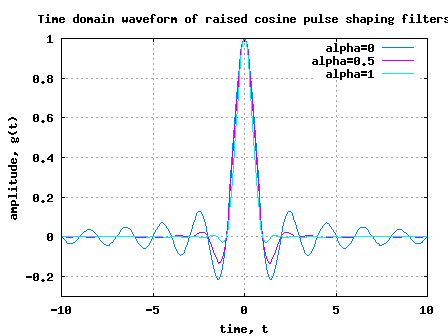
Figure: Time domain response of raised cosine pulse shaping filters
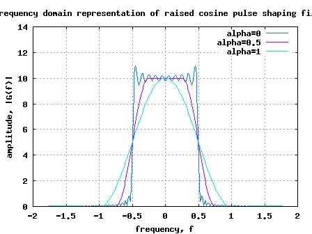
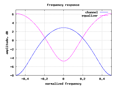
Figure: Frequency domain response of raised cosine pulse shaping filters
Observations
[PROS] From the time domain samples, can observe that filter tail of the raised cosine filter with greater than 0 dies down faster. This implies that practical implementations can ignore taps which are close to zero with negligible loss in performance.
[PROS] As the filter taps values at and above are close to zero, timing mis-alignmnet at the receiver does not contribute to significant inter symbol interference.
[CONS] As can be seen from the frequency response, with greater than 0, the fitler response is bandlimited only till
. We need a wider bandwidth to transmit the waveform when compared to classical Nyquist bandwidth.
Given that the raised cosine filtering simplifies the practical implementation (by making the receiver more robust to timing synchronization errors), the increase in transmission bandwidth may be a small price to pay.
Note
From the frequency domain response, one may observe that the shape of the roll-off looks like a cosine waveform having a DC value. Henec the term raised cosine filters. 🙂
Reference
[DIG-COMM-BARRY-LEE-MESSERSCHMITT] Digital Communication: Third Edition, by John R. Barry, Edward A. Lee, David G. Messerschmitt
Hope this helps.
Krishna

Your code gives the maximum value for frequency respoonse as Fs whereas it should be 1.
@Shradha: Isn’t that a case of applying the appropriate normalization? 🙂
sir
I want to use different types of filter like RC,SRRC and Gaussian at transmiter side .Is it possible to use same at receiver side or i have to use matched filter.Is it possible to get matlab code for SRRC , Gaussian and matched filter.actually i want to pass the data through different filter before channel and after channel want to use matched filter.
Regards
Divya
@Divya: In one of the recent posts on phase noise https://dsplog.com/2012/08/28/transmit-spectrum-phase-noise/, used a square root raised cosine filter.
os = 4;
% root raised cosine filter
t_by_Ts = [-4:1/os:4];
beta = 0.5;
ht = (sin(pi*t_by_Ts*(1-beta)) + 4*beta*t_by_Ts.*cos(pi*t_by_Ts*(1+beta)))./(pi*t_by_Ts.*(1-(4*beta*t_by_Ts).^2));
ht((length(t_by_Ts)-1)/2+1) = 1 -beta + 4*beta/pi;
ht([-os/(4*beta) os/(4*beta)]+(length(t_by_Ts)-1)/2+1) = beta/sqrt(2)*((1+2/pi)*sin(pi/(4*beta))+(1-2/pi)*cos(pi/(4*beta)));
ht = ht/sqrt(os);
Hope this helps
Hello sir
Thank u very much for your reply.Its really help in my project work.
Thanks once again.
Hi Krishna,
A very basic question. I understand how an RRC helps reduce ISI in baseband transmission where the the delay spread of individual pulses wil overlap without a pulse shaping filter. However I am unable to visualize an RRC in a wireless scenario where u wud hav a QPSK/QAM followin the RRC thereby transferrin da baseband info onto the carrier/s..If the pulses produced by the RRC filter are not the ones being actually transmitted, how does an RRC filter help?..
I understand that this might be a silly question but its really bugging me. Would really appreciate an answer..
Great blog btw!..
Thanks,
Neeraj
@Neeraj: We have an upconversion followed by a downconversion – and these cancel each other out. So the analysis for the passband is similar to the baseband story. I think Proakis describes that in one of the chapter’s, but cant find that right now.
I need to implement following paper in matlab..please help mee…its urget..
http://www.google.co.in/url?sa=t&source=web&ct=res&cd=1&ved=0CBgQFjAA&url=http%3A%2F%2Fieeexplore.ieee.org%2Fiel1%2F31%2F504%2F00009919.pdf%3Farnumber%3D9919&ei=ug_SS5HtHor46QOAn-y8Dw&usg=AFQjCNFci8QpmcOlT7_HPGYQbiEMTHB2RQ&sig2=vI1G_fj02WSthdf7wXsh7A
@vishram: You can post your queries in the comments section. I will try answer to the best of my understanding
hi,
what about raised cosine hilbert ist true that
raised cosine hilbert=raised cosine filter+ analytic signal?
thanks
@yasmine: Sorry, did not understand your query
i need ds cdma simulation and mc cdma simulation in matlab with ber calculation.plz help me…..
@pawan: Sorry, I have not tried modeling MC-CDMA systems
Hey Krishna
I am trying to make a QPSK and OPQSK Modulation and Demodulation using Matlab. Can you tell me how to get started on this? I have no clue how to start it. What are the things I need to start it. So if you can send me an email at my email address listed above, your help will be appreciated.
Thank you,
Bhargav Sur
Hi,
What will happen to my ber if i am having sampling frq 16 and my filter taps are 20 instead of 16, and down sampling is at 16 again?
What will happen to my ber if i am having sampling frq 16 and my filter taps are 8 instead of 16, and down sampling is at 16 again?
–BE
@BE: Sorry, did not understand your query.
If I use your code (where you use fs=10). For example, I want to cyclic shift 1/2T the gt_alpha5.
Will it be (where I shift 1/2*10?):
gt_shift=gt_alpha5[6:201 1:5] ???
Is this right? This may be very basic for you but I am learning to understand this. Thanks.
@Shanti: Seems right. Good luck.
Hi,
Could you give me the guidance/information how to cyclic shift the RRC signal (t-1/2T)?
@Shanti: Hmm, let me try with an example.
Lets say, you have 20 element vector to cyclic shift x[1:20], the the cyclic shift by 5 elements means x[16:20 1:15]. Agree?
Hope this will answer your query
In your code are the cofficients of filter normalized to 1?
@vikas: No, if you see the frequency response of the filter, we can see a passband gain of around 10.
hi…
If 1 var Qpsk symbol is transmitted and RC pulse shaped then what is the energy of the transmitted pulse?
acc to to rectangulat Matched filter the transmitted energy of symbol needs to be 1 but with RC I am not able to find the transmitted energy if it is one??
And if the transmitted energy is not 1 then why we are transmitting more energy?
@VIkas: If you make the passband gain of RC pulse shape to be 1, then the transmit energy will also be one.
Hi Khrisna,
If I want to use the square root cosine, can I use the code below for the Matlab?
Beta=0.5;
N=64; %ifft size
m=0:1:N-1;
A=2*Beta/(pi*sqrt(N));
B=1-((4*Beta*m/N).^2);
Sin1=sin((1-Beta)*pi*m/N);
sincDen=4*Beta*m/N;
sincDenZero = find(abs(sincDen) < 10^-10);
sincOp = Sin1./sincDen;
sincOp(sincDenZero) = 1;
Cos1=cos((1+Beta)*pi*m/N);
BZero = find(abs(B) < 10^-10);
rrc1=(Cos1+sincOp)./B;
rrc1(BZero) = 0;
rrc=A.*rrc1;
May I know why do you use the range -fs:1/fs:fs and not 0:1:N-1 in the time domain?
Thank you.
@Ray: I quickly ran the script and from the waveform of the variable rrc, something seems to be wrong. Though I cannot pin point what is wrong. The usage of term -fs : 1/fs : fs is to model the effect of sample spacing.
why upsampling is needed before the application of raised cosine filter ?
@shama: With a sampling frequency of fs, we can “see” frequencies from [-fs/2 to fs/2). As we would want to see a wider frequency range prior to application of raised cosine filter, we upsample.
heye, why would we need a matched root raised cosine filter at receiver side at all. its purpose is to minimize intersymbol interference right! so once the signal has been transmitted over the channel with good why would we need to filter it again?
@mujtaba: Yes, there is an advantage in using root raised cosine in receiver. Typical receivers have additive white gaussian noise and matched filtering helps one to maximize the signal to noise ratio in that scenario.
Matched filtering is an operation where the received signal + noise is convolved with ‘known’ transmit signal shape (time reversed, complex conjugate to be precise).
https://dsplog.com/2009/05/08/ber-with-matched-filtering/
In typical systems we use Root Raised Cosine as the transmit pulse shaping filter, followed by Root Raised Cosine filter in the receiver. This ensures that the total frequency response is ‘Raised Cosine’ resulting in no ISI plus ensuring that the SNR is maximized.
I am wondering what is the relationship between the truncated length and roll-off factor ? Do you have any reference on that ?
Also, in practice, the truncated length is determined by the complexity of the filter or by the roll-off factor used ?
Thanks in advance.
@MMSE: Well, if we want to have faster roll off (in frequency domain), the we need to use more taps (more taps = higher length).
In practice, I think we will have constraints on the spectral response (i.e roll off). Based on that constraint, we will chose the filter with minimal length which can achieve that. Makes sense?
Thanks. There was a bug in the code after all 😛
Hi, I have a basic question regarding raised cosine filtering. Why do we have to upsample the data before applying such a filter? I’m currently experimenting with these things in Matlab and I noticed that spectral images are created, which I believe are due to upsampling the signal. Is this effect desired? None of my books seem to mention anything about the need of upsampling, yet the Matlab functions require it. Maybe I’m missing something obvious! 🙂
@243kof: When you are sampling at fs, the spectrum from [-fs/2 till fs/2] gets repeated at integer multiples of fs. Quite likely, this is the spectral images which you are observing.
With a sampling of frequency of fs, the spectrum which we can ‘see’ is only from [-fs/2 to fs/2]. Any spectrum outside this frequency band gets folded back into the this band.
However, when we are doing transmit filtering, our objective is to ensure that we filter the transmit signal effectively. Hence before doing filtering, we do upsampling to a higher frequency and then filter. When we are upsampling to a higher frequency, we can now ‘see’ a wider frequency range and can control its spectrum via filtering.
In general,
(a) when upsampling (increasing the sampling frequency) we insert zeros between samples and then filters (also called interpolation).
(b) when downsamplig (reducing sampling frequency), we filter and then remove samples (aslo called decimation)
The theory on decimation and interpolation is detailed in Chapter 10 Multi Rate Signal Processing of DSP Proakis
Hope this helps.
Hi Krishna
I have a doubt, Is the root raised cosine filter at the receiver side is nothing but the Matched filter ?
So the chain from the Tx to Rx is
Tx bits –> Transmit filter (RRC) —> channel —-> Receive filter (RRC) —> detection process
Is it correct ?
Thanks in advance
bijoy
@bijoy: Yes, the root-raised-cosine at the receiver is a matched filter (matched to root raised cosine in transmitter).
I have provided my thoughts on why we use root raised cosine instead of raised cosine as a reply to a comment from @giri.
The chain which you have described is correct.
Hope this helps.
thanks
Giri
Chankara,
any advantage in SRRC at TX + SRRC at RX instead of RC at TX & only sampling at RX ? Bluetooth standard uses SRRC
Giri
@giri: Yes, there is an advantage in using root raised cosine. Typical receivers have additive white gaussian noise and matched filtering helps one to maximize the signal to noise ratio in that scenario.
Matched filtering is an operation where the received signal + noise is convolved with ‘known’ transmit signal shape (time reversed, complex conjugate to be precise). In typical systems we use Root Raised Cosine as the transmit pulse shaping filter, followed by Root Raised Cosine filter in the receiver. This ensures that the total frequency response is ‘Raised Cosine’ resulting in no ISI plus ensuring that the SNR is maximized.
You can see a nice description of matched filtering using rectangular pulse shape in the wiki entry @
http://en.wikipedia.org/wiki/Matched_filter
Hope this helps.
@umar: This just means that the oversampling factor is 10x. In typical systems one may find oversampling of 3x to 4x. The oversampling factor depends on the signal bandwidth which inturn depends on the symbol rate (and not directly on the modulation size)
In typical systems, one may find filtering by root raised cosine filter at the transmitter followed by root raised cosine filtering in the receiver. The objective is to make the total system transfer function as a raised cosine response.
One need not nullify the effect of raised cosine filter. Raised cosine filtering does not distort the desired signal if the sampling location is exact.
Sir,
Can you please provide some material related to root raised cosine filter,that will be very helpful for me to design a FIR RRC filter.
Thankyou.
@Saurabh: I have not tried discussing root raised cosine filter. I just briefly know that the filtering is split between the transmitter and receiver by having a root-raised cosine filter at each end.
You may find the wiki discussion on it @ http://en.wikipedia.org/wiki/Root-raised-cosine_filter
Hope this helps.
Hi,
I have a basic question again and it is about the range t/T which you have kept as [fs:1/fs:fs] where fs=10.Any reason for that? Is there some criteria, which is the best range. I mean is this range can be different for QPSK or 16QAM.
My other question is that when you have want to transmit the QPSK (say) symbols than what is the procedure. Do we need to convolve the raised cosine filter taps with the data symbols at the transmitter side and what do we do at the receiver side to nulify the effect of raised cosine filter.
Regards,
umardar