PAM (Pulse Amplitude Modulation) is one of the simplest ways to send digital data. In this post, we start with baseband PAM, look at its spectral efficiency, and then move on to passband PAM — which turns out to be less efficient. To fix that, we explore how QAM (Quadrature Amplitude Modulation) improves efficiency by using both sine and cosine carriers. This leads to I/Q modulation, and the corresponding IQ demodulation with Python code.
The content is based onSec 5.2.1 of [DIG-COMM-BARRY-LEE-MESSERSCHMITT].
Baseband PAM transmission
Consider a simple baseband transmission where the information is sent by modulating a pulse. This can be represented as
, where
is the symbol period,
is the symbol to transmit,
is the transmit pulse shaping filter,
is the symbol index and
is the output waveform.
Pictorially the same can be represented as,
Figure: Baseband PAM transmission
Minimum bandwidth for ISI free transmission
According to the Nyquist zero ISI criterion, to transmit data without intersymbol interference (ISI), the pulse shaping filter must satisfy,
This ensures that each symbol appears cleanly at its own sampling instant without interference from neighboring symbols. For this condition to hold and still remain bandlimited to , the ideal pulse shape is the sinc function:
This result comes from the fact that, with ideal sinc pulse shaping, the entire symbol stream can be perfectly reconstructed if the channel passes all frequencies up to . This is also consistent with the Nyquist–Shannon sampling theorem, which states that to fully reconstruct a signal sampled at
, the signal must be bandlimited to
.
Thus, if we use ideal (bandlimited) pulses like sinc functions, the entire baseband PAM signal can be confined within:
Figure: Spectrum of baseband PAM (with symbol rate )
Spectral Efficiency
Spectral efficiency is a measure of how efficiently a communication system transmits data over a given bandwidth. It is defined as the number of bits transmitted per second per unit bandwidth, typically expressed in bits/second/Hertz.
Assuming that PAM signal uses
distinct amplitude levels, each symbol carries
bits. When each symbol takes
seconds to transmit, the bit rate of the system is:
Substituting the bit rate and bandwidth into the formula for spectral efficiency, we get the spectral efficiency of baseband PAM as.
Code
Python code for passband PAM transmission with pulse shaping by rectangular filter and sinc filter.
Passband PAM transmission
Now, consider that the baseband PAM signal is upconverted to a carrier frequency by multiplication by a cosine carrier. The transmitted passband signal is:
The spectrum of the passband PAM is as shown below,
Figure: Spectrum of passband PAM
When the baseband signal is multiplied by , this modulation shifts the entire spectrum up to be centered around the carrier frequency
.
The frequency range of the signal becomes:
Thus, the total bandwidth needed by passband PAM is,
Spectral Efficiency of passband PAM
As earlier, assuming that PAM signal uses
distinct amplitude levels, each symbol carries
bits. When each symbol takes
seconds to transmit, the bit rate of the system is:
Substituting the bit rate and bandwidth into the formula for spectral efficiency, we get the spectral efficiency of passband PAM as,
Can see that spectral efficiency of passband PAM is half of baseband PAM.
IQ Modulation (QAM for improving spectral efficiency)
As seen earlier, passband PAM suffers from reduced spectral efficiency. To improve spectral efficiency, we exploit the orthogonality of sine and cosine carriers. This leads to Quadrature Amplitude Modulation (QAM), where two independent data streams are modulated:
- to a cosine wave (in-phase component, I)
- to a sine wave (quadrature component, Q)
Because sine and cosine are orthogonal over a symbol period , these two streams do not interfere and can be perfectly separated at the receiver. As a result, QAM doubles the data rate over the same bandwidth compared to passband PAM.
The transmit signal with passband QAM is represented as,
where,
and
are the in-phase and quadrature data symbols, respectively
is the carrier frequency
This signal requires the same bandwidth as passband PAM, however carries twice the information.
Note :
The factor of is included to normalize the total power of the passband QAM signal to unity. As cosine and sine carriers each contribute only half the power
when modulating a baseband signal, multiplying each arm by
ensures that the modulated in-phase and quadrature components retain their original baseband power.
For notational convenience, we express the passband signal using its complex baseband equivalent,
,
where
This forms the I-Q modulator circuit.
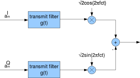
Figure: IQ modulator
IQ demodulation
The received passband signal is split into two branches and multiplied with cosine (in-phase, I) and sine (quadrature, Q) carriers. Each branch is then passed through a matched low-pass filter, typically matched to the transmit pulse shape, to extract the baseband I and Q components. The resulting streams are then independently sampled and demodulated to recover the transmitted symbols.
Downconversion
Let the received passband signal
where,
To extract the I and Q signals, multiply with local carrier signals :
In-phase branch:
Similarly, for the quadrature branch:
After downconversion, each branch (I and Q) contains the desired baseband signal components, along with unwanted high-frequency terms centered around .
Low-pass Filtering
To isolate the desired baseband signals, we apply a low-pass filter (LPF) to both the I and Q branches. This filter passes frequencies within the baseband bandwidth (usually where
Matched Filtering
After low-pass filtering, we apply a matched filter to each of the I and Q branches. The matched filter is designed to maximize the signal-to-noise ratio (SNR) at the symbol sampling instants. It is typically a time-reversed and conjugated version of the transmit pulse shape .
If the transmit pulse was a rectangular or truncated sinc or raised-cosine shape, the matched filter is also a rectangular or truncated sinc or raised-cosine, respectively. This ensures:
- Maximum energy concentration at symbol instants
- Minimization or elimination of inter-symbol interference (ISI)
The output of the matched filter is then sampled every and
.
This sequence completes the demodulation chain for QAM and ensures that both spectral shaping and ISI suppression are achieved in the receiver.
The IQ demodulator can be visualized as shown in the figure below
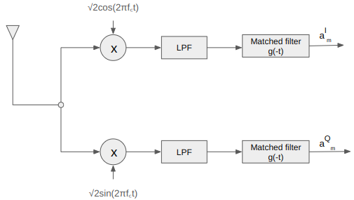
Figure: IQ demodulator
Code
Python code for passband qam with rectangular and sinc pulse shaping filter, followed by low pass filtering and matched filtering.
When compared to the transmit symbols, can see that there is a spread in the received symbols. Using raised cosine or root raised cosine filters is a potential approache to mitigate this.
Summary
The post covers the following key aspects
- Spectrum of Baseband PAM with a code example
- Reduced Spectral Efficiency of Passband PAM
- Sending information on orthogonal sine and cosine carriers to improve efficiency (passband QAM)
- IQ modulator and corresponding demodulator for Passband QAM with code
Another approach for improving the spectral efficiency of passband PAM is to filter away half the bandwidth (which is not carrying any ‘extra’ information). This is called Single Sideband Modulation (SSB). Anyhow, as I-Q modulation is simpler to implement than circuit for filtering away half the spectrum, I-Q modulation stays. 🙂
Have any questions or feedback? Feel free to drop your feedback in the comments section. 🙂
Reference
[DIG-COMM-BARRY-LEE-MESSERSCHMITT] Digital Communication: Third Edition, by John R. Barry, Edward A. Lee, David G. Messerschmitt
Hi Everyone,
I think I,Q transmission and receive system is just one way of baseband data transmission. Any baseband signal can be broken up into I and Q components. There are other forms of transmitters also known as polar transmitter. But in real circuit implementation polar transmitters are hard to build. Its very tough to change the phase of carrier precisely. But by using I,Q one can adjust the phase just by varying amplitudes of I,Q.
@Maxsteel: Thanks
written in simple way.. easy to understand:) it helps a lot.. thank you:)
Hi!. How the source coding can compress the data rate?And how the modulation schemes are able to increase the data rate,though we are representing the symbol with redundant bits?Can u plz put forward the process of digital communication with an example?
@komal:
a) Source coding : If we have redundancy in the information symbol, we can have a better way of sending that information out (rather than sending the raw data). For eg, if we have a sequence [0 0 0 0 0 1 1 1 ], we can alternatively send [ 4 zeros three ones] 🙂
b) Modulation : We can pack more bits into a symbol. However, the penalty is that we need higher signal to noise ratio to recover the bits.
Hi evry one in this.Nice to c u all here buddy’s.
Ofcourse I am new to this. I have a small problem with my calculation in OFDM USING QAM AND IQ modulator .
I ll just paste the question here. I have done some calculations, but i was unable to judge those.Please help as early as possible.
We are required to build a SIMULINK model of a 16-QAM OFDM Digital Communications System (OFDM transmitter and OFDM receiver) operating over an AWGN channel.
• The OFDM system has a cyclic prefix of 20% of the (data) symbol duration Ts.
• Use an I-Q modulator at the transmitter and I-Q demodulator at the receiver to upconvert and downconvert, respectively, the analogue signal to a central frequency of fc=2 MHz (so, the passband transmitted signal is centered on 2 MHz).
• The symbol duration is set to Ts =1 msec.
• Chose the number of carriers, N, so as to achieve a bitrate of Rb = 192000 bits / sec (you have to evaluate the correct N).
• Test the system performance for Eb/N0=5, 8, 10, 12 and 14 dB, and report the respective BER measurements.
• Subsequently, use a channel encoder of your choice and repeat the BER measurements for the same values of Eb/N0.
Hi krishna,
good work on your posts. I have a small question on the IQ modulator, Since we were previously not utilizing the other half of the spectrum in passband transmission and hence introduced the IQ scheme to fully use the bandwidth, does it mean we are actually sending the same data (data symbol) in both I and Q arm? i.e if its a1, then its a1 carried in both arms?
@kwame: Well, its not that we were not utilizing the other half of the spectrum. Rather the same information (mirrored in frequency) was present in the other half of the spectrum. In previous case, we were not sending anything on the Q arm.
can you give me some programm for cognitive radio
@mhamdi: Sorry, I do not have posts on cognitive radio
Hi,…can anybody guide me in making an FM transmitter and receiver on Simulink and System Generator and its implementation on Lyrtech SFF SDR DP…. 🙁 i dont kno how to do it for implementation 🙁 kindly do help me
@Umair: Sorry, I do not have experience with Simulink. Anyhow, am planning to write a post on FM transmission/reception in the near future.
thanks for replying bhayya..ya actually now a days they r using it seems.. actually am doin my final year of engg.. and am doin a project based on this.. i have a thought.. can u inform ur mail id so that i can put it up to u and u can suggest the necessary corrections bhayya..i ll be pleased if u can help me out.. hope am not disturbing u…
hi…. the article on iq modulator was good… i have a small doubt. how can we generate a FM signal usig this iq modulator
@pradeep: Thanks. I have not studied the FM transmitter well enough to comment. Just a quick thought: do we need I/Q modulator for FM.
Yes.. the last post very informative. Please incorporate more pictures and explanations than the MATH. Great work though!!
@MY MAN: Thanks, feedback taken 🙂
@Simon : Oh, that means my way of explaining failed. 🙁
Let me try again.
It is known that a sine wave and a cosine wave with period T are orthogonal to each other,
i.e. integral_over T sin(wt)*cos(wt) = 0
This means we can send independent information on sine wave and cosine wave and be able to recover both of them at the receiver with out any distortions. This forms the crux of IQ modulation. We send the information I on cosine wave and Q on sine wave.
What is the advantage? Ofcourse – double the data rate. 🙂
What is the flipside? We need double the bandwidth. If we send only on sine or cosine, the spectrum is symmetric. We need to send information only on one side of the spectrum. However, with IQ modulation spectrum is no longer symmetric.
Does this explanation help to address your concern?
Krishna,
“Some time back, a friend mentioned that he is yet to understand the need for having both in-phase (I) and quadrature-phase (Q) signals in typical wireless systems”
I wonder if you could please show me some info on this understand, I am still confused why we need I and Q?
Thank in advance, Simon
@Muthukrishnan: Well, I do not quite follow your statements.
If the symbol rate is 1/T and modulation is BPSK, then
(a) bandwidth requirement in baseband is -1/2T to +1/2T.
(b) bandwidth requirement in passband is fc-1/2T to fc OR fc to fc+1/2T
So one would think that the since passband requires only a single sidedd spectrum, I would think that the noise bandwidth is smaller in passband. Do you agree?
Hi krishna,
The SNR of a transmitted signal in baseband is given by (assuming a binary
or 2PAM)
SNR = (R*Eb) / (B*No/2)
Where R – bit rate and B – bandwidth of baseband signal (i.e., if the
baseband signal is ranging from 0 to 10 KHz then I am taking B= -10 to 10
kHz= 20KHz).
Am i right?
So if I am transmitting the same bit rate in bandpass I need 2B (positive
20 KHz and negative 20 KHz )bandwidth which leads to,
SNR = (R*Eb) / (B*No)
So when I convert a signal from baseband to bandpass with the same bitrate
, the SNR will come down by half. Is this inference correct?
or am I assuming something wrong.
I am learning a lot from your website. More importantly the relation between theory and practice. Its really helpful.
Keep up your good work.
Bye
@Didi: Thanks for the link 🙂
I’m using GNURADIO plattaform to implement SDR for OFDM transceiver.
http://www.gnu.org/software/gnuradio/
Nice link Krishna. You can see that the book I have recommended is being cited in a number of articles in this link. But as you can concluse from these articles, SDR is about building a configurable transceiver using software.
Thanks again for the link.
@Yahia. Thanks for the information.
I just happened to see an SDR Overview article in DSPDesignline.com
http://www.dspdesignline.com/207401351?cid=RSSfeed_dspdesignline_dspdlRSS
Here are two definitions of SDR:
1- a radio that is substantially defined in software and whose physical layer behavior can be significantly altered through changes to its software
2- The software radio is a radio which employs one wideband analog to digital converter (ADC) with a resource of programmable digital signal processors (DSPs) to service an entire spectrum allocation in a single integrated module
Now the first one is taken from Jifferey Reed book of Software Radio which I recommend for interested readers. it is titled “Software Radio: A Modern Approach to Radio Engineering ”
To make it clear, SDR is a configurable wireless platform that can change its personality using software “channel frequency, modulation, data rate, transmission power and many others”
Now the ability to sense and “make decisions” to change personality to an appropriate format is called cognitive radio. So in simple words, cognitive radio =SDR+intellegence
I have the following link that has a nice collection of links about SDR:
http://www-sop.inria.fr/planete/SoftwareRadio/
What are you doing these days
@tabraiz: idling… try to come back to posting 🙂
@Yahia: Yes, it would be interesting to share thoughts.
Quick q: When we say SDR, is it
(a) the RF center frequency which is getting dynamically programmed ?
(b) the baseband processing adapting to various modulation schemes?
OR is it the SDR concept too vast to encapsulate in the above bullets?
Unfortunately not Krishna 🙁
My work on SDR is part of my research for PhD. But I will be happy to share my work with you. I am using an SDR platform from Lyrtech. At any case I will be happy to discuss any issue about SDR with you. There is a coming standard called 802.22 which will be a cognitive radio based standard. If you are interested, we can exchange ideas and information about these topics.
Thank you for your interest and for answering my questions
@Yahia: Thanks. 🙂
Do you have a website where information about your work is presented? I would be keen to have a look and get a feel about the work on SDR.
Great job! this website is very impressive. I am working on digital commincations for SDR and I have added this website to my top favorites. Keep it up and thank you for all your efforts.
Hi Krishna, really a very helpful explanation. Please keep this good work going
Hi Yahia, I had also started working on SDR using GNU Radio platform. If possible, can you please drop me a mail at somya1104@gmail.com so we can discuss our respective works.
@Johny: No worries. I typically do not get disturbed by questions. 🙂
Hi
yeah thank you very much now its clear… i hope u dont get disturbed by my questions but i really want to clear things up
@johny:
What we want to transmit is
s(t) = aI cos(2*pi*f_ct) – aQsin(2*pi*f_ct)
It is reasonably intuitive to see that above equation is equal to
real part of (aI + jaQ)*(cos(2*pi*f_c*t) + j*sin(2*pi*f_c*t)). Do you agree?
Hi
thanks… but why do we want to consider only the real part?
thankyou very much for your reply please clear this query. I shall be very thank to you …
@ Johny: Thanks. Ofcourse, you can shoot in your queries. I will try answer to the best of my knowledge.
The symbol R stands for real, which means the output takes only the real part of s(t) e^{j2*pi*f_c*t).
Helps?
Krishna
Hi,
I have been reading your topics they are very good and helping me alot. I request you not to stop this good work. I am new to this field so i might ask you alot of foolish questions bt thts how i will learn… in the above derviation can you please tell me what this ‘R’ symbol (in the equation very after this line …notational convineance, the above signal can be represented mathematically as,) means? why are we using it? I didnt understand it please explain thanking in advance…
tc