In this post, let us try to derive the symbol error rate for 16-PSK (16-Phase Shift Keying) modulation.
Consider a general M-PSK modulation, where the alphabets,
are used.
(Refer example 5-38 in [DIG-COMM-BARRY-LEE-MESSERSCHMITT])
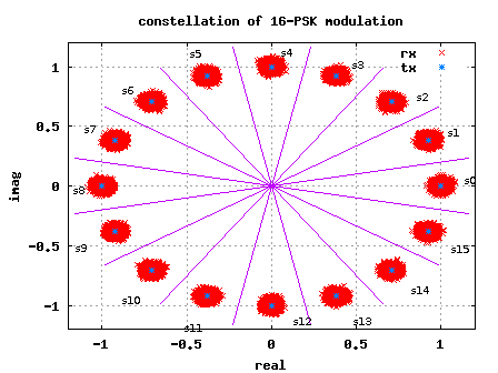
Figure: 16-PSK constellation plot
Deriving the symbol error rate
Let us the consider the symbol on the real axis, i.e
.
The received symbol .
Where the additive noise follows the Gaussian probability distribution function,
with
and
.
The conditional probability distribution function (PDF) of received symbol given
was transmitted is:
.
As can be seen from the figure above, due to the addition of noise, the transmitted symbol gets spreaded. However, if the received symbol is present with in the boundary defined by the magenta lines, then the symbol will be demodulated correctly.
To derive the symbol error rate, the objective is to find the probability that the phase of the received symbol lies within this boundary defined by the magenta lines i.e. from to
.
For simplifying the derivation, let us make the following assumptions:
(a) The signal to noise ratio, is reasonably high.
For a reasonably high value of , then the real part of the received symbol is not afected by noise i.e.,
and
the imaginary part of the received symbol is equal to noise, i.e.
.
(b) The value of M is reasonably high (typically M >4 suffice)
For a reasonably high value of M, the constellation points are closely spaced. Given so, the distance of the constellation point to the magenta line can be approximated as
.
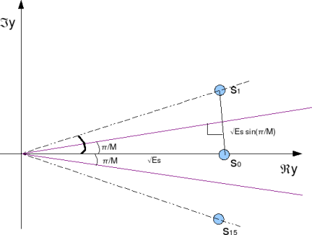
Figure: Distance between constellation points
Given the above two assumptions, it can be observed that the symbol will be decoded incorrectly, if the imaginary component of received symbol
isgreater than
. The probability of
being greater than
is,
.
Changing the variable to ,
.
Note: The complementary error function, .
Similarly, the symbol will be decoded incorrectly, if the imaginary component of received symbol
is less than
. The probability of
being less than
is,
.
The total probability of error given was transmittd is,
.
Total symbol error rate
The symbol will be in error, if atleast one of the symbol gets decoded incorrectly. Hence the total symbol error rate from M-PSK modulation is,
Simulation model
Simple Matlab/Octave script for simulating transmission and recepetion of an M-PSK modulation is attached. It can be observed that the simulated symbol error rate compares well with the theoretical symbol error rate.
Click here to download: Matlab/Octave script for simulating symbol error rate curve for 16 PSK modulation
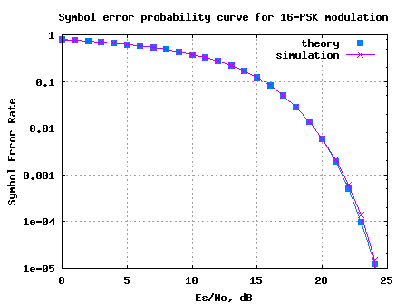
Figure: Symbol Error rate curve for 16PSK modulation
Hope this helps. KrishnaReferences
[DIG-COMM-BARRY-LEE-MESSERSCHMITT] Digital Communication: Third Edition, by John R. Barry, Edward A. Lee, David G. Messerschmitt
please help me in MATLAB simulink for rain attenuation and graphiical user interface . at least the block diagram . am MSC student
@abdelfatah : sorry, i do not have simulink and have not also not studied about rain attenuation
please help me by giving me the Symbol Error Rate (SER)/ Bit error rate formula/Equation for 16-APSK modulation. because i need the theoretical equation for plotting and compare simulation result.
waiting someones feedback
@imran: sorry, i have not discussed 16APSK schemes in the posts
Dear Mr. Krishna
I want to develop a MATLAB code for MIMO using MMSE equalizer for 4X4 antenna configuration and using BPSK, QPSK and 16-QAM modulation. Suggest me any MATLAB code for reference.
I hope you will reply me.
@Ravi: You can check out posts on MIMO at
https://dsplog.com/tag/mimo
Most of them discuss 2Tx-2Rx IID Rayleigh channel system with BPSK case
Hi,
Why did you use N=10^5 a big number?
@NH: To get a good average in symbol error rate….
sir,
i m doing b.tech in ece branch from bit mesra. i need a code for finding symbol error rate of bfsk signal in presence of additive gaussian noise.
please help me out in this.
@abhijeet: Does this post on frequency shift keying with coherent demodulation help?
https://dsplog.com/2007/08/30/bit-error-rate-for-frequency-shift-keying-with-coherent-demodulation/
Hello, I have a problem that I need to solve about a
modulation algorithm. I’m working on a assignment and need a code in Matlab to the
in-phase and quadrature components of a 16 QAM. Afterwards, I will run the
program in a Vector Signal Analyzer and I will have to see the I and Q waveforms
and the constellation.
I have been trying out by creating an array with 16 values (0 to 15) and
converting them to binary (0000 to 1111), afterwards, I have created the I and Q
signals, as a sine or cosine of the array values mentioned respectively using a
for loop, thus creating the different values for the phase, but I don’t know how
to express the amplitude levels (-3, -1, 1, 3).
I would appreciate if someone could lend me a hand in this problem.
Thanks in advance
@lyla: You can generate random 16QAM constellation points, pass them through a pulse shaping filter and then feed to the VSA
hi~~Krishna
i have a question~~~
in the matbla source code~
ipPhasehat=2*pi/M*round(opPhase/(2*pi/M))
i don`t know why you use this code~~~
anyway thank you for your efforts~
@Moongeun: To round the received phase to the nearest constellation point.
Hi Krishna,
i`m an MSc communication systems engineering student in the university of portsmouth, i would love to be a member of this forum and there is this problem i want to solve:
Analysis & Simulation of 16PSK Using
MATLAB.
OBJECTIVES:
· Demonstrate the ability to learn MATLAB for the purpose of this
coursework
· Write a technical report describing the principle, theory and applications
of 16PSK. Your system will be tested over the AWGN Channel.
· Implement a MATLAB simulation of 16PSK modulator and
demodulator system.
· Measurement of the symbol error rate and bit error rate as a function of
the ratios Eb / No and Es / No achieved by the system in the presence of
additive white Gaussian Noise. Your measurements should be compared
to the theoretical estimates that you should have derived from first
principles.
· Show that you are able to identify and use technical references.
But for now am learning MATLAB and the problem is giving me though time, i wish you can help me by putting me through with the rest apart from the MATLAB. Please sir i need your help.
Regards.
Tukuben
@Tukuben: The following posts maybe helpful to you
https://dsplog.com/2008/03/18/symbol-error-rate-for-16psk/
https://dsplog.com/2008/05/18/bit-error-rate-for-16psk-modulation-using-gray-mapping/
I am an MSc mobile, personal and satellite communication student in university of westminster, london. i like to be member of this forum
@abdulmaleek: There are two options:
1. You can subscribe to the email newsletter by providing you email address in the form on the top right of the page. Email subscription will entitle you to receive the free e-book on error rates in AWGN.
2. Further, you can join via Google FriendConnect option provided in the bottom of the page. Google FriendConnect enables you to share the contents of this blog to your friends/colleagues in an easier fasion.
Hope this helps.
sir
i am doing ME in digital communication. please refer me any project in MATLAB coding related to my subject.also suggest any reference material for MATLAB study
@gautam: Maybe you can try modeling the transmitter, receiver and channel per the 3GPP LTE specifications? It includes MIMO, advanced coding scheme, OFDMA etc. Quite a lot to learn. 🙂
@Rajesh:
1. If the device is non-linear, one would expect that the signal at the output will have more frequencies than the signal at the input (generation of harmonics dye to x^2, x^3 terms etc).
The out-of-band frequencies maybe filtered out, however nothing much can be done about the harmonics in the in-band. It may be that the measured power includes both out-band and in-band harmonics (along with the desired signal power), hence the C/N does not degrade. However, since the in-band harmonics are not deisrable for demodulation, there is degradation in the MER.
2. When you say ‘devices not matched’, I would think that you are referring to impedence mismatch between the devices (resulting in reflection…). May I suggest the generation of in-band and out-band frequencies due to impedence mismatch as a probable reason for MER degradation.
Does this perspective makes sense? Thanks for these nice questions… 🙂
Dear Krishna
Thanks for the reply. While you are right, however we will have to add the noise level. Now the noise level at room temp will be about 3 dBuV while that for QPSK with MER of 15 dB at Signal strength of 86dBuV will be approx 71 dBuV. So that the additive White noise is negligible. We also find that C/N does not get deterioted as we pass thru varios devices.
However we have noticed that MER doe reduce by 0.7-1.0dB.
Question is
1. If thye device contains diodes then if at the point of operation diode is non linear it can add to the reduction of MER but not of C/N. How MER is related to non-linear CSO and CRB.
2. If the device is poorly matched then agian MER measurement will get affected. How does the mismatch between the device and the instruments affects the MER?
Reagards
Rajesh Kher
@ Rajesh:
1. By definition modulation error ratio (and not rate) is,
MER, dB = 10*log10(average transmit symbol power/average error power) where
error is the distance between the transmitted and received constellation.
If we consider that the received symbol Y is
Y = S + N, where S is the transmitted symbol, N the noise.
then error = Y-S = N.
From the above equation, it is reasonably intuitive that modulation error ratio (MER) is comparable to signal to noise ratio (SNR) in noise only scenario.
In the presence of other impairments, MER will reflect the distortions in the constellation due to phase noise, IQ imbalance, frequency offset etc.
Slides 20-22 from http://chapters.scte.org/cascade/SCTE%20CNR%20vs%20SNR.pdf will be useful
2. Is your question the following: If we pass a received symbol with a noise of xdB
through a splitter having resistive loss of 1dB, how much will be the resultant noise
power. Did I interpret correctly?
I would say the resultant noise will be 10*log10(10^(-x/10) + 10^(-1/10))
Did the linear addition of two noise components, do you agree?
Regards,
Krishna
Krishna
1. The symbol error rate should also be related to Modulation Error Rate (MER). Since MER is what most Meters measure a correlation will be most helpful.
2. Most of the signal are distributed over a network. What one also needs is the MER impairments due to network elements.
For example if the signal is split into two parts. That splitter will have an insertion loss which will have a spatial component. For example a 2 way lossless splitter will reduce the signal and noise by 3 dB and hence will not impair the signal. However there is an associated resistive loss aboput 1 dB. How much will the MER deteoriate?
Regards
Rajesh Kher
@mahesh:
Yeah… i agree. it takes a bit of time to get used to 20*log10() or 10*log10() … 🙂
My rule of thumb is as follows:
(a) for voltage signals use 20*log10()
(b) for power signals use 10*log10().
In the code, as you observed,
(a) for scaling noise, which is a voltage signal, I used the 20*log10().
(b) for finding the theoretical symbol error rate, the Es/No in dB (which is signal power by noise power), the conversion used is 10*log10().
Hope this helps.
Regards,
Krishna
In your simulation, you have added noise voltage/level i.e taken 20log10(ns) whereas for calculating theoretical BER , you have used noise power. (10log10(ns^2)). I always tend to get confused between these. Do you know any study material clarifying these and some examples?
thanks
mahesh
@mahesh: true. Infact in the transmit and receive chain, there are various sources which can introduce DC (LO leakage etc). Given so, it makes it difficult to recover information present on DC subcarrier.
@ Rajesh, How do you get sync information from DC?
@ rajesh:
well, typically dc subcarrier is not used (as far as I have seen). Can you please point to the section in the spec (and the spec version).
Thanks,
krishna
hi i am doing M.E wireless tech. now i am doing my final sem project is implimentation of synchronization algorithem for wimax ieee 802.16e standard.
in wimax ieee802.16e standard
for synchronization purpose they are using preamble .in that preamble they using dc subcarrier .why they are using dc subcarrier… please if any one knows clarify my dought…its urgent
with regards
rajesh neelakandan