From the previous post on OFDM (here), we have understood that an OFDM waveform is made of sum of multiple sinusoidals (also called subcarriers) each modulated independently. In this post, let us try to understand the estimation of frequency offset in a typical OFDM receiver (using the short preamble specified per IEEE 802.11a specification as a reference).
Understanding frequency offset
In a typical wireless communication system, the signal to be transmitted is upconverted to a carrier frequency prior to transmission. The receiver is expected to tune to the same carrier frequency for downconverting the signal to baseband, prior to demodulation.
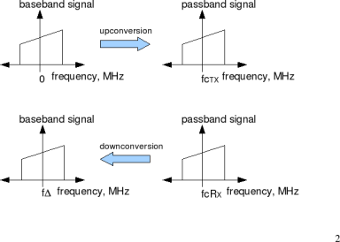
Figure: Up/down conversion
However, due to device impairments the carrier frequency of the receiver need not be same as the carrier frequency of the transmitter. When this happens, the received baseband signal, instead of being centered at DC (0MHz), will be centered at a frequency , where
.
The baseband representation is (ignoring noise),
, where
is the received signal
is the transmitted signal and
is the frequency offset.
Frequency offset estimation in 802.11a OFDM preamble
From the IEEE 802.11a specifications (Sec 17.3.3), it can be observed that each OFDM packet has a preamble structure formed using 10 short preambles of duration each. This short preamble is constructed by defining 12 subcarriers only (out of the available 52 subcarriers) where the modulation of individual subcarriers ensure a low peak to average power ratio.
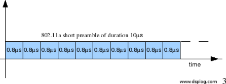
Figure: OFDM short preamble 802.11a specification
From the equation defined in the previous section,
.
Given that short preamble is perodic with ,
.
At the receiver as both and
are known,
.
Taking angle() of both sides of the equation
.
So, the frequency offset is,
. 🙂
Simulation model
Simple Matlab/Octave script simulating generation of 802.11a short preamble, introducing frequency offset of 200kHz and estimating frequency offset is provided. Click here to download.
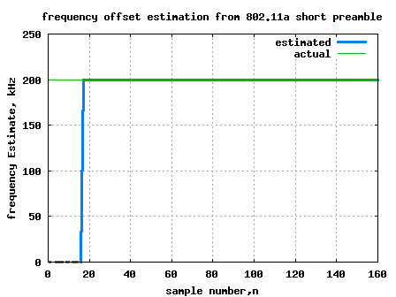
Figure: Plot of frequency offset estimate using 802.11a short preamble
As can be observed starting from sample number 17 (i.e. after ) and till samples number 160 (
) the frequency offset estimate is available. For improving accuracy in the presence of noise, typically the output
is accumulated prior to computation of angle.
Maximum possible frequency offset which can be estimated
It is known that limits of the phase estimated by the angle() function is from . Plugging this to the above equation, the minimum value of frequency offset value which can be estimated is,
and the maximum value is,
.
From Sec17.3.9.4 (of IEEE 802.11a specification), the center frequency tolerance is . With a carrier frequency of 5.8GHz, this specification corresponds to a frequency offset within the range
. Thankfully, this is within the ‘estimatable’ range of frequency offsets which which can be estimated by the short preamble 🙂 .
Note:
We have not discussed the effect of inter carrier interference (ICI) between the sub-carriers which happens in the presence of frequency offset. Maybe we can discuss in a later post.
References
Hope this helps.
Krishna
sir,
why 10 short preambles are used?
@achuse: The 10 short preambles correspond to around 8us. This gives time for the receiver packet detection, automatic gain control loop (AGC), frequency offset estimation etc
Thank you sir,
for the frequency estimation the time difference between two short preambles are enough? so for frequency estimation no need of 10 preambles?
@achuse: ideally, two short preambles are enough. however, to get better noise averaging one would go for accumulation over a longer window
thank you sir
hi dear Krishna and friends
please help me, I urgently need a MATLAB program for simulation ofdm channel estimation based on (Block or Comb)-Type Pilot in AWGN channel and fading(flat and frequency-selective) channel using LS(Least Square) & ZF(Zero Forcing) & MMSE(Minimum Mean-Square Error) or MLSE(Maximum Likelihood Sequence Estimation) algorithms.
thanks for fast response
Hi, can you please explain how you have assumed the sampling frequency to be 20 MHz ? How will changing the sampling frequency affect the frequency offset value estimated ?
@Vamsikrishna: with a sampling frequency of fs, the range of frequencies which we can ‘see’ is from [-fs/2, fs/2). Ideally, the change of sampling frequency should not affect the value of frequency offset which is estimated. However, if the sampling frequency reduces, it can happen that higher value of frequency offset can cause the phase to wrap around [-pi,pi).
respected experts,
can anyone send me the matlab codings for estimation of frequency offset in awgn channel using ofdm technique
Hi Krishna;
Thank you for you post. One thing that I wanted to check was if what you were trying to do there is a cross-correlation between the transmitted signal and the offset-ed one since the offset here is affecting the whole OFDM symbol and not an Inter carrier offset. So it was in this order: 1. Cross-correlation between the transmitted (after applying the ifft) and the offseted signal, 2. Applying the fft of the result to estimate the delay ?
Thx
@Baal Hadad: Well, the idea in this post is not doing cross-correlation. Its correlating the received signal with a delayed version of itself.
Hello Krishna, I have a short question with the matlab code. Why is the “inputFFTShortPreamble” designed like that? How this design make sure that all the 10 short preambles (each with 16 samples) are identical?
@Erick: If we look at the frequency response of the short preamble, we can find that one out of four subcarriers are populated. Its like oversampling by 4 in the frequency domain, and this results in 4 repeated bunch of 16 samples in time domain.
@Krishna: ok, I see. Thanks very much.
One further question 🙂
One out of four subcarriers are populated in the frequency domain for the “inputFFTShortPreamble”. These 12 subcarriers are set to either “1+j” or “-1-j”. I think this is for the purpose of having low PAPR. But when I changed the first “1+j” to “1-j” and the last “1+j” to “-1+j”, the result curve is totally incorrect. The estimated FO becomes zero for every 8 samples numbers.
What’s the reason?
@Erick: I think once you give the estimate the time to settle (16 samples), find that the estimation is accurate. Is that the case with you too?
@Krishna: My case is that for some of the sample points, the estimate FO is zero, which is not the case cause we set the FO to be 200Hz.
I checked the code and preambles, I found one problem that by changing the first “1+j” to “1-j” and the last “1+j” to “-1+j”, some sample points become zero. That is why the estimate FO is zero, because when you multiply the zero’s conjugate by zero, the results are zeros and then the angle are zeros.
Anyway, I think this is not related with the estimate time. But it is related with the design of the preambles. The preamble, which is 160 samples, has 10 repeated short preambles and none of the 160 samples should be zero.
Am I right?
@Erick: Oh, ok. Having zeros in the time domain samples is not a good idea.
please tell me how the training symbol reduces the synchronization,please explain .
@preet: Using the training symbol, the receiver can estimate frequency offset, channel etc which helps to achieve synchronization with the transmitter.
Hi Krishna,
I need to customize wavelet packet decomposition by iir filter design,but I don’t know how to do it?
@Haleh: Sorry, am not familiar with wavelet decomposition
Hi Kirshna,
I am simulating FO estimation and compensation in OFDM system. I add AWGN noise in the transmission, then introduce FO, lastly, estimate the FO but it fluctuates very much (have negative and positive FO). I sum all of them and divide to take averaging result but not accurate.
How to improve the accuracy?
@Tien Dzung: Try averaging the complex number which is used to estimate the phase (which corresponds to frequency offset).
Hi Kirshna,
I wondering if you could help in this problem.
I want to add the Sampling Frequency Offset (SFO) in my OFDM system simulation. I believe that I should do that in time domain, but dont know exactly how???
I apperciate you help
Regards
@SARA: Well, I also have not discussed addition of sampling frequency offset in the model.
Hi Krishna, nice article, helped me a bit to implement a similar frequency estimation algorithm.
In your matlab script the computation of op seems unnecessary complex though. How about (didn’t test this in matlab for typos)
% estimating frequency offset
op = conj(yt(1:end-0.8*fsMHz)).*yt(1+0.8*fsMHz:end);
fdeltaEstimatekHz = -1*angle(op)/(2*pi*0.8*1e-6)/1000;
Do you see my point?
Cheers, Ole
i am doing my project on same topic..
iam implementing “CARRIER FREQUENCY OFFSET ESTIMATION FOR OFDM SYSTEMS USING NULL SUBCARRIERS”
IEE TRANSACTIONS ON COMMUNICATIONS VOL 54 NO 5.. MAY 2006..
I need badly matlab code for this paper can u send to my gmail..
@murali: Sorry, no 🙂
@Nils Ole: As long as they are mathematically equivalent, any coding style will do
thanks for Your Explanation
I understand now.
@Ichen: Glad
The ariticle is good.
But something is wrong, right?
$y(t-\delta t) = x(t – \delta t) * e^{}$
not
$y(t-\delta t) = x(t) * e^{}$
@Ichen: Thanks.
The catch is
x(t – \delta t) = x(t) ; as the preamble is periodic with \delta t = 0.8us.
Agree?
Hello Krishna.
How to decide the CFO value in Hard Decision Parallel Interference Cancellation for uplink OFDMA ?
an example:
BER performance for N=64, K=a, CFO=[-0.09 0.1 -0.08 0.05]
for the journal:
Lakshmish R, “Hard Decision Parallel Interference Cancellation for uplink OFDMA “
Hi.Will frequency offset value varies in accordance with the cyclic prefix?
@pc: Well, no. The frequency offset is modelled as
y(t) = x(t)*exp(j*2*pi*f_delta*t)
Hi Krishna,
Help me out.Kindly explain the graph in detail.
@Sundari: The graph plots the estimate of the frequency offset versus time (sample)
Thank u krishna….
Hello Krishna.
Can you make a comparison on BER for OFDM sysytems With and Without CFO estimation
@Emmanuel: Without CFO estimation and compensation, the BER will be poor. I have a post on Inter Carrier Interference in OFDM due to carrier frequency offset
https://dsplog.com/2009/08/08/effect-of-ici-in-ofdm/
Hi,
Can you please tell me how to remove the residual frequency offset using pilots in ofdm. The initial frequency offset removal is insufficient in the presence of noise and you know how much sensitive this ofdm is to frequency offsets.
If you have any guiding material or link related to it, please tell me that too.
Thank you.
@jenna: I have not discussed the pilot based residual frequency offset estimation. The algorithm is reasonably simple – due to frequency offset, the samples undergo a linear phase change in time domain = constant phase shift in frequency domain. As we know the reference phase (as the pilots are known), we can take the average of the phases from multiple pilot subcarriers to compute the constant phase shift in frequency domain.
Hi! Krishnan Sir, May I know the various methods of calculating Frquency Offset in OFDM systems
@Selvi: I have discussed one method here. Can you please share your thoughts on other methods.
I mean of course a real system in the question above. And one more question, how do we calculate the frequency offset in ppm if there is a IF stage ? Does it accumulate somehow before processing in baseband ?
Regards
@joel: Well, evenif there is an IF stage, at the baseband level, it does not matter. At the receive baseband, we are trying to find out the frequency offset introduced by all RF stages.
Dear Krishna,
does the oscillator on the receiver side have a constant frequency offset or is that rather a drift ? If its a drift, is there a possibility to track it without sending repeatedly the preamble ? I mean sth. like sending the preamble and then track it with help of pilots ? Do you see any problems with estimating the frequency offset in case of MIMO systems or Alamouti scheme ?
Thank you !
@joel: Typically, we assume constant frequency offset. Even after frequency offset correction, there will be error and those error are tracked using pilots.
No problems for frequency offset estimation in MIMO schemes.
Thank you for the reply Krishna. Considering the frequency noise which varies in time (like AWGN), is it also tracked and corrected in real systems or is it just a design parameter and can not be corrected ?
Regards
@joel: Typically frequency offset remains constant through out a packet (which can be in the order of 3-4 milli seconds). Frequency offset is corrected and tracked – else the BER impact on OFDM systems is high.
hey karishna just want your help regarding Frequency offset estimation using 802.11a short preamble
i got your program but in that u have introduce frequency offset just in the short preamble my question is we have to
introduce frequency offset in the whole data stream or just in the short preamble and why????
another thing which i wnt to discuss is that in ur articl u have written that ” It is known that limits of the phase estimated by the angle() function is from [-pie,+pie] ” … what if it is greater thn pie?????? in the paper mentioned below , given the solution for such case but i really cant understand =( can u plzzzzzzzzz help me out ……
“Robust Frequency and Timing Synchronization for OFDM
Timothy M. Schmidl and Donald C. Cox, Fellow, IEEE”
and also how to correct the freq offset?????
@Sadaf: My replies:
1/ I used only short preamble as that was sufficient for the topic under discussion. For introducing, frequency offset for the rest of the time domain samples, just multiply by exp(j*2*pi*fd*t)
2/ If its greater than [-pi, pi), it will wrap around to a value within [-pi,pi) range
My Dear Krishna Sankar
please you have information about Wavelet packet in OFDM, can you help me?
@Ali: Sorry, I do not know about wavelet packet in OFDM. Good luck.
Question,
When your taking angle of both sides, “Taking angle() of both sides of the equation”.
The solution drops out |x(t)|^2. What happens to this term. Looks like I am missing something obvious here. Unless the preamble is designed to have unity power .
@jamal: The term |x(t)|^2 is a real number and hence angle is zero. Hence that term does not play a role in the angle computation. Agree?
hi krishna
i m new to ofdm. i m a M.E communication systems final yr student.
i m doing myproject regarding blind CFO estimation.i have one doubt that how to find the SNR for my estimate
@Nisharani: From the received signal, I guess you will be having a rough idea of your signal power. Further, you will be aware of your noise floor too. Both the values should help you compute the SNR.
hye krishna,
i am a new user and working on dvb-t assignment in my uni,i have just 1.5 months time,my assignment here is to transmit on ofdm signal by using dvb-t parametre and then introduce any error by means of either awgn channel or anything and the part which i have to do is to implement the synchronisation technique which can remove the frequency offset,
i am really depressed by this cuz no time left.will be able to help me out.
ofdm transmission and reception is found here from the
http://www.ece.gatech.edu/research/labs/sarl/…/OFDM/Tutorial_web.pdf
i have to introduce the frequency offset in this code and then remove the frequency offset by means of anything like , resampling, pilot symbol method or guard insertion method etc.
hope u will be able to help me out.
@syed: The link is not working. Does the DVB-T has a periodic preamble type sequence in time domain? If yes, you can adapt the approach discussed in this post to estimate frequency offset.
Dear Krishna, When you are going to post (1) Timing offset estimation and (2) The effect of ICI between the sub-carriers which happens in the presence of frequency offset.
@Kamran: I will add these to my to-do list. Quite likely I will post about effect of ICI in another two weeks.
The preamble duration should be 8us
@cc: Its indeed 8us. Please pardon the typo in Figure. Though I showed only 10 short preambles of 0.8us, I incorrectly wrote in the legend as 10us.
hi krishna,
if there is carrier offset, will it not affect detection using 10 short symbols …i reckon there are 10 peaks at a distance of .8us at the output of matched filter and what effect carrier freq offset has on those peakes?
@gaaza: Yes, in presence of carrier offset, the peak to side lobe ratio at matched filter output will become smaller as the reference signal does not include the effect of carrier offset. However, note that autocorrelation power is not affected by carrier offset.
While looking at matlab code i got one small doubt. Why you havenot used conv function instead of for loop for y(t)*y(t-x)
operation?
@sandeep: For the y(t)*y(t-x), we cannot use the convolution operation. OR do you think otherwise?
Remember reading somewhere that autocorrelation and convolution operation are related. Need to check it again. I will check the text and come back.
@sandeep: I think I follow your perspective. You are right, there is a relation between autocorrelation can be described as convolution a signal with time reversed copy of the signal. Note that, autocorrelation output is computed all values of delay. However, in this example we are finding for only ONE value of delay (viz 0.8us).
Does that help?
Thank you krishna.
I understand it now.
@MUTHUKRISHNAN:
The variable outputiFFT is of length 64 samples and each short preamble is of duration 16 samples.So the total is 4 + 4 + 2 = 10 short preambles.
On the second part of your question:
Typically it depends on the specification. Short preamble is constructed as defined above. Long preamble is constructed by appending 1.6us worth of samples.
Hope this helps.
Hi krishna,
I am new to OFDM and I am using all your programs and articles to get a better understanding of the concept. In the matlab script , the following lines
“% concatenating multiple symbols to form 10short preamble
outputShortPreamble = [outputiFFT outputiFFT outputiFFT(1:32)]; ”
you have said that you are forming 10 short preamble but the code is concatenating only two symbols and half of the thrird symbol. How does it account for 10 symbols.
Can you give me a hint on what that peice of code does?
I have got another question, if I am going to transmit an OFDM data with 10 short preambles and then 2 long preambles, do I have to add prefix to all the 12 training symbols individually?
Than you.
@Bheema: As I understand, using virtual carriers for frequency offset estimation is an iterative computational intensive process, hence not typically used in 802.11a.
Having said that, big plus of using virtual carriers is that it has a bigger estimation range. So, in cases where the frequency offset is large a coarse estimate using virtual carriers + fine estimate maybe warranted.
Infact, while at Stevens Institute of Technology, I worked under the guidance of Prof. Tureli to demonstrate experimentally the frequency offset estimation using the virtual carriers. The summary can be found here –
U. Tureli and K. M. Pillai, “Analytical and Experimental studies on carrier frequency offset estimation algorithms for OFDM systems,” in 37th IEEE Asilomar Conference on Signals, Systems and Computers (Asilomar’03), Nov. 2003, vol. 1, pp.174-178.
BTW, are virtual carriers used in practice for frequency offset estimation in 802.11a
@Bheema: Note that the transmitter can have a +20ppm and receiver a -20ppm offset. Hence the estimation capability should be 5.8e9*40e-6/1e3 = +/-232kHz.
In your example for the frequency offset, 20ppm for 5.8Ghz center frequency, the frequency offset should be +/- 116kHz
Yes, me too had the same doubt. I expected +/-116kHz
@Murali: The +20ppm at 5.8GHz causes 116kHz. However, note that for the worst case transmitter can have +20ppm and receiver can have -20ppm, resulting in a total of 40ppm difference between the tx and rx
@ Abishek: Thanks. I have added your blog to my blogroll too.
Krishna, your blog is also added in my blog roll, so that visitors can come here too…
Hey Krishna! Thanks for visiting my blog & commenting. Btw, i won’t be here in B’lore during that time…hoping to meet you next time at some other event…till then, keep blogging!