Minimum shift keying (MSK) is an important concept to learn in digital communications. It is a form of continuous phase frequency shift keying . In minimum phase shift keying, two key concepts are used.
(a) The frequency separation of the sinusoidals used for representing bits 1’s and 0’s are , where
is the symbol period.
(b) It is ensured that the resulting waveform is phase continuous.
Motivation of continuous phase
In a previous post (here), we have understood that the minimum frequency separation for two sinusoidals having zero phase difference to be orthogonal is , where
is the symbol period. However, it can be observed that at each symbol boundary, there is a phase discontinuity. The presence of phase discontinuities can result in large spectral side lobes outside the desired bandwidth. Hence the need for having a frequency modulated signal which is phase continuous.
Phase growth in MSK
To ensure continuous phase, the phase of the carrier of the MSK signal is
, where
is the symbol period,
corresponds to -1 for bit 0, +1 for bit 1 respectively.
The corresponding carrier signal is
.
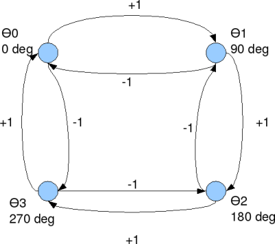
Figure: Phase transition diagram for MSK (Ref: Fig10.22 in [COMM-PS]
Simulation Model
Simple Octave/Matlab code for simulating and plotting binary Minimum Shift Keying is kept here.
Next steps
We have observed that bit error probability of classical coherent binary frequency shift keying is 3dB poorer compared to bit error probability of binary phase shift keying. However, in minimum shift keying, using the knowledge of the phase transitions, we should be able to recover the 3dB loss associated with FSK and get a performance comparable to BPSK. We will hopefully discuss that in a future post.
Reference
[COMM-PS] Communication Systems Engineering, John G. Proakis, Masoud Salehi
i want matlab code for reduction of ICI in ofdm using raised cosine pulse.
please can you send it my email id.
thanks
@ABHIJEET: Does your OFDM system has cyclic prefix. If the fitler response is bounded within the cyclic prefix, then there should not be any ICI.
https://dsplog.com/2008/02/17/cylcic-prefix-in-orthogonal-frequency-division-multiplexing/
https://dsplog.com/category/ofdm/
Hi Krishna, can you show examples for OQPSK with sine pulse shaping using modem.oqpskmod and modem.oqpskdemod? thanks!
@riki: Sorry, I do not have Matlab installed in my home computer.
I found my problem, it sufficed to use a coefficient of Rayleigh for 1 bit and not for the 8 samples, thank you anyway for the help
@Denis: Ok
sir could u pls snd me matlab code for msk+convolution using awgn channel
@baljit: Hope the post on MSK transmitter and receiver helps you
https://dsplog.com/2009/06/16/msk-transmitter-receiver/
Sorry to ask again, but have you an explanation of the difference found in relation to the theory for the simulation of MSK modulation in a Rayleigh channel, thank you
First, Thanks for your help !!
Now I try to simulate MSK (and FSK) transmission on a rayleigh channel.
With your exemple at : BER for BPSK in Rayleigh channel, I do the same thing with the MSK /FSK modulation but the results are different from theory (There is a small gap)
Can you explain it, do you have the same gap?
Thank you again for your help!
In fact, I try to program in C + +, the MSK modulation, your Matlab model is very interesting however I have some difficulties in receiving, the convolution does not work very well. Have you an idea how to demodulate the signal by taking into account the phase change?
I think that I perform the convolution in reception is not suitable, I convolves my outgoing signal channel signals with AWGN: f1 = sqrt (2 / T) * cos (2 * PI * (k +1 / 4T ) * t) and f2 = sqrt (2 / T) * cos (2 * PI * (fc-1/4T) * t).
But the results between the two convolutions are not different enough to determine correctly received bits.
What do you think?
Thanks for your help !
@Denis: I can point you to a post where I discussed MSK transmitter and receiver
https://dsplog.com/2009/06/16/msk-transmitter-receiver/
In this post, I have discussed MSK as a variant of offset QPSK.
Hi,
thanks for your explain !
Also can you explain me, how you do to demodulate the signal, I have difficulties to demodulate correctly because I do not take into account the phase to the convolution of signal reception. It is difficult because we have 1 phase for each point (fsamp in reality) of the signal.
Thanks for your help and sorry for my english !
@Denis: Sorry, I do not quite understand the concern. Did you take a look at the Matlab model in the post.
Ok, but how does the receiver looks like ?
What about carrier and phase recovery ?
How I get my signal back ?
@Hans-Werner: I have a follow up post on the MSK receiver @
https://dsplog.com/2009/06/16/msk-transmitter-receiver/
However, I have assumed that synchronization is perfect and we need not do carrier/phase recovery.
Hope this helps.