Thanks to the nice article from Xilinx TechXclusives [XLNX-TECH], let us try to understand the probable digital implementation of resistor-capacitor based low pass filter. Consider a simple RC filter shown in the figure below. Assuming that there is no load across the capacitor, the capacitor charges and discharges through the resistor path.
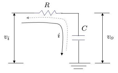
Figure: RC low pass filter
is the voltage at the input of resistor and
is the voltage at the output.
From capacitor theory, the charge in the capacitor is , where
is the capacitance
is the voltage and
is the constant current flowing for short duration of time
.
With the input voltage is greater than output voltage
, resulting in current
flowing through the resistor
, where
.
When this current flows into the capacitor for a short time , the capacitor will charge and the voltage across the capacitor increases to
, where
is the new value of output voltage.
Digital Implementation
The above equation seems to be convenient for digital implementation as shown in the equation below:
where,
,
is
,
is
and
is
.
The transfer function of the above equation is
.
Simulation model
Script for plotting the frequency and step response of a digital RC low pass filter.
Click here to download.
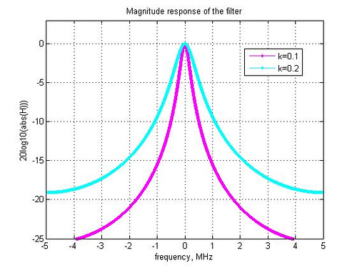
Figure: Frequency response of the digital implementation of RC low pass filter
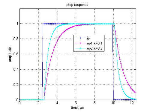
Figure: Step response of the digital implementation of RC low pass filter
Observations
1. As expected, lower the value of k, tighter is the frequency response and slower is the settling time. This is in synch with analog RC implementation, where a higher value of R and C suggests that the capacitor takes more time to charge/discharge (Note that k is inversely proportional to RC).
2. To facilitate simpler digital implementations not involving multipliers, the value of k can be chosen to be a power of 2.
References
[XLNX-TECH] Xilinx TechXclusives: Digitally Removing a DC Offset (or “DSP Without Math?”), By Ken Chapman Senior Staff Engineer, Applications Specialist, Xilinx UK.
Hope this helps.
Krishna
You will find the artile now in this white paper:
http://www.xilinx.com/support/documentation/white_papers/wp279.pdf
@Henk: Thanks for the link. I updated the post.
Hello Sir,
Do u have a C program for the above? It would be really great if u can provide the C code for my project purpose.
Thanks and regards,
Raj
@raj: Sorry, I do not have the C code