Given that we have discussed symbol error rate probability for a 4-PAM modulation, let us know focus on finding the symbol error probability for a QPSK (4-QAM) modulation scheme.
Background
Consider that the alphabets used for a QPSK (4-QAM) is (Refer example 5-35 in [DIG-COMM-BARRY-LEE-MESSERSCHMITT]
).
- Download free e-Book discussing theoretical and simulated error rates for the digital modulation schemes like BPSK, QPSK, 4–PAM, 16PSK and 16QAM. Further, Bit Error Rate with Gray coded mapping, bit error rate for BPSK over OFDM are also discussed.
- Interested in MIMO (Multiple Input Multiple Output) communications? Click here to see the post describing six equalizers with 2×2 V-BLAST.
- Read about using multiple antennas at the transmitter and receiver to improve the diversity of a communication link. Articles include Selection diversity, Equal Gain Combining, Maximal Ratio Combining, Alamouti STBC, Transmit Beaforming.
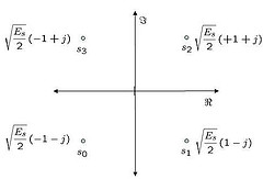
Figure: Constellation plot for QPSK (4-QAM) constellation
The scaling factor of is for normalizing the average energy of the transmitted symbols to 1, assuming that all the constellation points are equally likely.
Noise model
Assuming that the additive noise follows the Gaussian probability distribution function,
with
and
.
Computing the probability of error
Consider the symbol
The conditional probability distribution function (PDF) of given
was transmitted is:
.
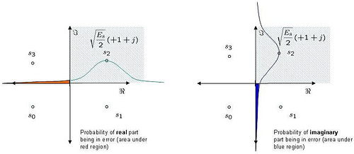
Figure: Probability density function for QPSK (4QAM) modulation
As can be seen from the above figure, the symbol is decoded correctly only if
falls in the area in the hashed region i.e.
.
Probability of real component of greater than 0, given
was transmitted is (i.e. area outside the red region)
, where
the complementary error function, .
Similarly, probability of imaginary component of greater than 0, given
was transmitted is (i.e. area outside the blue region).
.
The probability of being decoded correctly is,
.
Total symbol error probability
The symbol will be in error, it atleast one of the symbol is decoded incorrectly. The probability of symbol error is,
.
For higher values of , the second term in the equation becomes negligible and the probability of error can be approximated as,
Simulation Model
Simple Matlab/Octave script for generating QPSK transmission, adding white Gaussian noise and decoding the received symbol for various values.
Click here to download: Matlab/Octave script for computing the symbol error rate for QPSK modulation

Figure: Symbol Error Rate for QPSK (4QAM) modulation
Observations
1. Can see good agreement between the simulated and theoretical plots for 4-QAM modulation
2. When compared with 4-PAM modulation, the 4-QAM modulation requires only around 2dB lower for achieving a symbol error rate of
.
Reference
[DIG-COMM-BARRY-LEE-MESSERSCHMITT] Digital Communication: Third Edition, by John R. Barry, Edward A. Lee, David G. Messerschmitt
Hope this helps.
Krishna
Can anybody please send the MATLAB code for Probability of missed detection vs Threshold and SNR under different fading channels.Send code to bsivakumar100@gmail.com.
Thanks in Advance
b. Siva kumar Reddy
hello,
I want MATLAB code for LMS channel estimator and LMMSE channel estimator in OFDM. Can anybody send me please, bsivakumar100@gmail.com
how about the equation for BER and SER QPSK on AWGN channel ?
i’ve been searching on many literature,and they said the equation for BER is Pb=Q(√(2Eb/No)) and SER Ps≈2Q(√(Es/No))
are you agree with that equation ?
@miltung: The symbol error rate for QPSK is discussed in
https://dsplog.com/2007/11/06/symbol-error-rate-for-4-qam/
The bit error rate for BPSK is discussed in
https://dsplog.com/2007/08/05/bit-error-probability-for-bpsk-modulation/
sir please send me book in which theoretical and simulated error rates for the digital modulation schemes like BPSK, QPSK, 4-PAM, 16PSK and 16QAM are discussed
@Balaram: emailed you the instructions
Hello sir,
Can u please tell me the formula/expression of BER(bit error rate) in terms of SNR ( signal to noise ratio) for QPSK of AWGN channel. The above mention expression is for Symbol error rate.
and then why this formula for BER of AWGN avowed Pb=Q(√(2Eb/No)) and SER Ps≈2Q(√(Es/No)) ?
@afin: conversion from symbol error rate to bit error rate is reasonably simple.
a) Es/N0 = k*Eb/No where,
– Es/N0 is the symbol to noise ratio,
– k is the number of bits in the symbol and
– Eb/N0 is the bit to noise ratio
b) Probability of a bit in error is Probability of a symbol in error by number of bits k i.e.
Pb = Ps/k
https://dsplog.com/2008/06/05/16qam-bit-error-gray-mapping/
sir please send me book in which theoretical and simulated error rates for the digital modulation schemes like BPSK, QPSK, 4-PAM, 16PSK and 16QAM are discussed
@siva : emailed you the instructions
Thnq @ Krishna sir
Your Report to ABC News was well received. The results of your first report show a marginal link for the wireless LAN and a strong link for the satellite connection. They have some new requirements and they want you to re-evaluate the application and make some trade-offs. Remember your consulting company had been asked to do an analysis to address enhanced coverage for the ABC News mobile van using wireless technology. They want to use wireless LAN technology with a local Access point for their reporters at the scene and a satellite connection to connect with the newsroom. Here are the characteristic of the system they want to use:
Transmitter & Receiver LAN Access point Satellite
Modulation QPSK at 10 Mbps Range+ 200m Range” 500km
Bandwidth is 5 MHz Power 100mwatts Power 1 watt
Noise figure is 3dB Transmit antenna gain 0 dB Transmit antenna gain 6 dB
Frequency 1800 MHz Receive antenna gain 0 dB Receive antenna gain 40 dB
Minimum error rate 10-5 Access point height 3m
They now want an updated report to ABC which includes:
a. They want to increase their data rate to 20 Mbps. They also want to improve the wireless LAN connection to support a probability of error equal to 10-5. You are to consider M’aryPSK and M’aryQAM as possible options. You are to do an analysis to show the link equations that show the received power and noise, the SNR, the Eb/No, and the resulting Probability of error. Recommend changes to the configuration that will support the performance. Compare several options and make a recommendation.
b. You realize that the addition of FEC coding can improve the performance. Identify a block code from Table 6.4 and show the coding gain for this code by plotting the Error performance before and after the code.You are to do a Matlab of your final choice to verify the performance as with your first report
c. Your overall recommendation of choices and performance and explain to ABC why these improvements will work.
can you help me to solve this problem?
Hello sir,
Can u please tell me the formula/expression of BER(bit error rate) in terms of SNR ( signal to noise ratio) for 4-QAM. The above mention expression is for Symbol error rate.
@Gurimandeep: Assuming a gray coded modulation, i.e each symbol error causes only one bit error, conversion of symbol error rate to ber should be relatively simple.
Pb ~= Ps/k, where
Pb is the probability of bit error
Ps is the probability of symbol error
k is the number of bits in each symbol (for 4QAM, k = log2(4) = 2)
Further, as each symbol is carrying k(=2) bits,
Es/N0 = k*Eb/N0, where
Es/N0 is the symbol to noise ratio and
Eb/N0 is the bit to noise ratio
Have discussed this in the post on 16QAM bit error rate with gray coded mapping. Please check out.
https://dsplog.com/2008/06/05/16qam-bit-error-gray-mapping/
Hi
Can you help me with the difference between these two equations?
1) SNR=exp(snr_in_dB*log(10)/10);
2)1) SNR=10^(snr_in_dB/10);
@Basco: Aren’t both the same? 🙂
In (1), the snr_in_dB is converted to the expontential base and then used. In other, the base is 10.
Quick example :
clear all; close all;
snr_in_dB = [-10:10];
snr1 = exp(snr_in_dB*log(10)/10);
snr2 = 10.^(snr_in_dB/10);
err = (snr1-snr2)*(snr1-snr2)’/length(snr1-snr2)
err_db = 10*log10((snr1-snr2)*(snr1-snr2)’/length(snr1-snr2))
= -304.56!!!
sir plz send the qpsk matlab code for satellite transponders
@tulsi: What is the modulation used for satellite transponders?
Hello I’m student in telecommunication engineering. I prepare my project of the end of studies.
I find problem of simulation Asymmetric QPSK. please help me
@Popy: Sorry, I have not studied asymmetric qpsk.
We strongly value ur support to students. Big salute !!
@No Need to know: thanks 🙂
sir please send me book in which theoretical and simulated error rates for the digital modulation schemes like BPSK, QPSK, 4-PAM, 16PSK and 16QAM are discussed
@khushi: emailed you the instructions
nice work sir krishna it helps me alot, and one thing more i want to ask from you that do you work on cooperative communicaton by using SER with BPSK modulation in AWGN. and by using OPTIMUM COMBINIG which incerease the SINR, if you have code of it than plz send me, i will be very thank ful to u for this..
@sana: Have not studied co-operative combining explicitly. But the following posts on diversity might be of help
https://dsplog.com/tag/diversity/
Hello Krishna sir,
I want to do SPECTRUM SENSNG USING ENERGY DETECTION IN COGNITIVE RADIO, i need MATLAB code for that, can you send me as early as possible. Any replies are accepted.
@siva: sorry, i do not have codes on that topic
QPSK modulation in Rayleigh channel with a mmse equalizer.. plz help
@Ritesh: Does https://dsplog.com/tag/mmse/ help?
hi,
How shall I express the symbol error probability of a 64-QAM modulation as an expression of the bit error probability?
Thanks for your help.
@Myaki: Hopefully the post on symbol error rate for a general M-QAM case will be of help
https://dsplog.com/2012/01/01/symbol-error-rate-16qam-64qam-256qam/
hi i want to make code of QPSK can you please help me out?
@AGHA: This post has an example code for symbol error rate for QPSK in AWGN
@karishna sankar…..
Brother you are doing very nice helping work for others here. I used to get help from your uploads and comments often. Its a wonderful platform to extend technical knowledge and expertise from this site. Thanks
Regards
Tahseen
dear sir,
please send matlab code for
BER for QPSK with hamming coding
@abhinav: Please look at
Hamming (7,4) code with hard decision decoding
https://dsplog.com/2009/09/29/hamming-74-code-with-hard-decision-decoding/
Thanks for nice program. and sharing.
In ur program, If you adjust the program for dB more than 20, the error will be zero then theory and simulation do nor follow each other
What is the reason? and what is the solution?
@Ali: To get sufficient number of errors, we need to simulate for more number of bits.
Hi
for QPSK on fading channel can this equation if ok for theoretical expression?
theorySer = 1-sqrt(snr_linear./(snr_linear+1));
@Abrar: Are you missing a 1/2 term?
You can find the BER for BPSK in Rayleigh channel @ https://dsplog.com/2008/08/10/ber-bpsk-rayleigh-channel/
dear sir i need mathlab code for ber performance analysis of mimo usind different spatial multiplixing schems
with best recards
@asmaa: I have discussed V BLAST and different equalizer types @ https://dsplog.com/tag/mimo
Hope that helps.
Hi,
I need the Matlab code example for simulation of BER vs SNR for M-ary 64QAM.
Could you help me?
regards,
Hassan
@Hassan: I have a post on 16 QAM Bit Error Rate @ https://dsplog.com/2008/06/05/16qam-bit-error-gray-mapping
Hope that helps.
hello sir,
i m doing a project on performance analysis of ofdm so i need a matlab code for designing transmitter receiver n their ber calculation for different snr..
i will b thankful if u help me..
@Bhargavi: Hope the post on BER with OFDM in AWGN will be of help.
https://dsplog.com/2008/06/10/ofdm-bpsk-bit-error/
Thanks for this, it really helped me understand. Do you have a similar article or know of a similar article that deals with the performance of 4-QAM (or 16-QAM) over a Rayleigh fading channel. Thanks so much.
@Jonanthan: I do not BER for 4-QAM in Rayleigh channel. However BPSK in Rayleigh channel is @
https://dsplog.com/2008/08/10/ber-bpsk-rayleigh-channel/
Hellol sir,
I also have the same query, can u tel me appproxmiately what should be the Eb/No at BER of 10^-3…???
I m getting BER=10^-3 at around 40dB..!!!
I ve used a 6-tap Rayleigh channel, and awgn noise as
n1=sqrt(1/Eb_No)*randn(1,(conlen));
please rply..
@mpworld: I have not tried simulating the case, and hence not sure about the number.
Hi Krishna,
Why we must use
yHat=y./h ?
I have no idea about it.
@Sandra: to undo the effect of the channel
hello krishna, how we put one program (principal program) for exemple in QPSK modulation , i want to create one program principal(imput parameters) and others program (one for modulation , one for demodulation …).
and when i want to excute for exemple modulation , i go on program principal and we excute directly the comand of modulation .
bref how to create an programm principal with other sous program
@david: To modularize the code, You can use functions in Matlab
Hi Krishna,
i found this SER for QPSK is really helpful for me as i m a beginner for DSP and thank you so much. But i m having some difficulties on BER for QPSK in Rayleigh channel with Additive White Gaussian Noise (AWGN)? Do u have any matlab code regarding this topic? Or will you be able to help me generate code? Tks in advance.
@Rebecca: Though I have not discussed BER for QPSK case, I have a post on BER for 16QAM @ https://dsplog.com/2008/06/05/16qam-bit-error-gray-mapping/
Hope this helps
Hello Krishna,
In many of your simulations, I see this term,
y = s + 10^(-Eb_N0_dB(ii)/20)*n;
where s is the transmitted symbol and y is the received symbol. The thing I dont understand is how we get this expression – 10^(-Eb_N0_dB(ii)/20) ??
I am trying to compare different modulation schemes and I want to do a fair comparison. I already did the scaling for the symbols. In order to assign the noise power, I have this expression:
snrdb=[1:15]
Eb = 1; % signal energy
snr = 10^(snrdb/10);
noise_power = E/snr;
and I apply normally distributed Gaussian noise as:
noise = normrnd(0,sqrt(noise_power/2))+1i*normrnd(0,sqrt(noise_power/2))
Will this help in making fair comparison of different QAM symbols regarding BER? or the value of Eb should change for each of the modulation schemes such as 2 for QPSK (2 bits) 4 for 16QAM? (4-bits) ??
@SJ: The 10^(-Eb_N0_dB(ii)/20) is the scaling factor for noise voltage.
In my simulations I make the energy of transmit signal s to unity, such that the term 10^(-Eb_N0_dB(ii)/20) reflects the Eb/N0
hi Krishna, can you show some examples on OQPSK? if it is possible the one used by IEEE 802.15.4? thanks!
@riki: I have not seen the standard 802.15.4. However, you can check the post on Minimum Shift Keying https://dsplog.com/2009/06/16/msk-transmitter-receiver/
hi Krishna, can you show some examples on OQPSK? thanks!
@riki: you can check the post on Minimum Shift Keying https://dsplog.com/2009/06/16/msk-transmitter-receiver/
Hi, I want to do the BER in QPSK in Matlab. But the problem is that when i take the data value in Matlab using randint function then it takes the equivalent values of qpsk but the problem is that how do i change them in to bits. i mean 3 for 11 and 2 for 10 and the 01 and 00. I will be grateful to you if you give me that process. With thanks.
@Hasan: The bit represented by each constellation is a notional mapping. You can assign each constellation point to take two points. Typically, people prefer to do Gray coded mapping such that adjacent constellation points differ by one one bit.
https://dsplog.com/tag/gray/
Could you please explain how u are taking the data values for qpsk in the line
ip = (2*(rand(1,N)>0.5)-1) + j*(2*(rand(1,N)>0.5)-1); %
as here I guess that you are generating a real or imaginery value for a single bit, for qpsk we should select 2 bits for a complex symbol generation.
@Abhijit: Am not generating the bits here. Am directly generating the random constellation points.
hi,
i have three questions;
the first one is the (sigma)^2=N/2 for the gaussian distribution, if it was just N what to change in the program;
the second one is if your y (received signal) was not= x (signal)+w(noise) but y=hx+w with h is a complex vector how to change in the program;
the last one we want to do the same thing calculating the error but this time using MMSE(minimum mean square error in order of SNR), what to do;
Thanks a lot;
@amira: My replies
a) change the scaling of the noise
b) you need to have equalization in the receiver. plz refer to post https://dsplog.com/2008/08/10/ber-bpsk-rayleigh-channel/
c) plz check https://dsplog.com/tag/mmse
Hi krishna sir,
I am trying for the ber -qpsk-rician channel i dont know what is the difference and where i need to change in the coding for the bpsk..so please send me reply sir.you are my hope
@shu: My replies:
1/ For QPSK, send data on I channel as well as Q channel
2/ I have not discussed Rician channel model
hi krishna..
u explained the relation b/w SNR and symbol error rate for QPSK,but if i want to get the relation b/e SNR and BER then what shoul i do n how do i proceed.In your another post u gave one relation between bit error and symbol error Pb~Ps/k.
can i use it directly in case of qpsk.
pls let me know
thanks.
Hi Krishna
i was trying to simulate qpsk in ofdm like the one you did for bpsk in ofdm. could you please help me. and also Rician channel as well , this for my project .could u help me please.asap
thanks
regards
thanesh
@thanesh: Hope you have finished the project by now. Changing the BPSK in OFDM to QPSK in OFDM case should have been reasonably straightforward.
a) BER for BPSK with OFDM in AWGN
https://dsplog.com/2008/06/10/ofdm-bpsk-bit-error/
b) BER for BPSK with OFDM in 10 tap multipath channel
https://dsplog.com/2008/08/26/ofdm-rayleigh-channel-ber-bpsk/
Hello Krishna,
1) how can i generate source symbols of the following constellation
( 1,0) ,(0,sqrt(3), (-1,0) and ( 0,-sqrt(3)). in matlab using randn.
I tried randsrc() but it did not help
2) It is necessary to have unit enery( normalized variance =1) for the generated symbols? What is the reason.?
Could you pls reply,
Thanks,
Kishore.
@Kishore: My replies
1) Try using randsrc() from http://octave.sourceforge.net/doc/f/randsrc.html
2) Unit energy is to ensure that we do a fair comparison when comparing different modulation techniques. Also, in typical transmitters, we do not want the power to jump when we change modulation schemes. So, we normalize the baseband transmission path to unity.
Nothing other than very useful blog………..
@dhanabalu: Thanks
NEED THE PROGRAM FOR CALCUKATING BIT ERROR RATE FOR MARY PSK
@KKK: Please check the posts
https://dsplog.com/2008/03/18/symbol-error-rate-for-16psk/ and
https://dsplog.com/2008/05/18/bit-error-rate-for-16psk-modulation-using-gray-mapping/
Good luck.
hello krishna
i was trying to simulate qpsk in ofdm like the one you did for bpsk in ofdm. could you please help me. thanks
@kiki: You can send me queries over email.
Thanks Krishna for ur decorated resource . u have given SER in this post but i need BER derivation for QPSK in OFDM with Rayleigh channel. Please help me.
@M_abs: If you assume Gray coding, each constellation error results in one bit error. Since each constellation has two bits, the probability of bit error is approximately probability of symbol error by 2.
Helps?
thanks very much krishna i have changed my code rate …
actually i was jus following the matlab
Communications Toolbox User’s
Guide” theres an example of rate 2/3 convo with 16 qam ..
may be it doesnt work with qpsk
@mak_m: Not sure. Anyhow, good luck.
thanks for replying krsihna .m not using puncturing . I have choosen this trellis from “Communications Toolbox User’s
Guide” theres an example of 2/3 with 16 qam , in the same way wen i tried this with qpsk…it works fine..and in the same style wen i changed it to 1/2 with poly2trellis(7,[171 133]); it doesnt work n moreover wen i modify the viterbisim.m (with bertool) to the trellis poly2trellis([5 4],[23 35 0; 0 5 13]) for 2/3 . it doesn work at all.. i dunno where m wrong?
can u plz help me on this..i can email u my code if u want
Many thanks in advance
@Mak_m: I do not understand your usage of poly2trellis([5 4],[23 35 0; 0 5 13]) for getting 2/3 code rate. As I understand from the convolutional code table provided in Chapter 8 of Digital Communication Proakis
a) K=5, {23, 35}_o is a rate 1/2.
b) For 2/3, may be you can try K=3, {27,75,72}_o (as provided in Table 8.2-8)
Hope this helps.
Hi, krishna ..
i have been working on viterbisim.m which is a built-in matlab example for understanding the ber tool.. i that i have tried to change the code rate to 2/3 with trellis structure of
t = poly2trellis([5 4],[23 35 0; 0 5 13]); but output ber graph is completely unexpected n highly fluctuated.. i m not working on simulink ..plz help me how can i resolve this issue ..
basically my project is on mimo-ofdm so far i have done ofdm transceiver which works ok without rayleigh which is like this
data source ->FEC(2/3)->qpsk->ofdm ……but i need to send bits in a loop for more accurate ber that is i dont have to guess in advance ! thats y i m working on viterbisim.m… plz help m i have hardly got 2months to submit it …
thanks in advance
@Mak_m: How are you achieving code rate of 2/3? Is it by puncturing? From your description, it seems you are changing the trellis structure to achieve 2/3 coding – and it does not sound correct.
Please check your code with rate 1/2 codes, and then try to migrate to rate 2/3.
Good luck.
what is the relation between BER or SER and Signal-to-Noise Ratio
@Ali: As you know, BER is the bit error rate and SER is a symbol error rate. Since a symbol can carry more than one bit, each symbol error might result in a more than one bits to be in error.
Hello,
Sorry if my question is not relevant to this article.
I am working on finding Packet error probability in 802.11n WLAN, here reference is made to coded bit error probability.
Can anybody tell me difference between coded bit error probability and bit error probability .
-Thanks in adavnce
Swetha
@Swetha: I did not understand the motivation behind asking for the difference between coded BER and BER.
Anyhow just to add that : most of the articles in this blog refers to symbol error probability or bit error probability. For finding Packet Error Rate probability, we will group N bits to form a packet, and flag that packet as error if anyone of the bit in that packet is in error (alternatively, one may use FCS to count the error too).
Isn’t coded means with FEC and uncoded means without FEC
@WirelessNewbie: Yes.
hi, I have a situation whr I have to estimate channel using pilot in OFDM system.
then, I calculate SER using ur SER technique for QPSK.
Y=XH’+N;-> X=Y/H’ ; H’ is the estimated channel and all parameters r in time domain. It works nicely
But the problem is when I use interpolation to have H’ for data blocks, and then try to get the SER, the result is very bad. However I am getting nice MSE curve after interpolation.
Do have any suggestion to improve SER with estimated channel?
Regards
@Rabbi: I believe you are using interpolation in frequency domain and you are getting a good MSE curve, but not a SER curve. Is there some phase error even after equalization?
Hi, thanx for prompt reply.
Actually I am doing interpolation befor fft demodulation (i.e in time domain)and m geting good MSE curve.
After estimating data channel I am trying to estimate data directly using FFT demodulation. I am not doing any phase error correction.
Do I need to do anything to compansate the phase errors?
🙂
@Rabbi: Oh, you are interpolating in time. Are you computing the mean square error in time domain OR frequency domain? May I propose you to compute MSE in frequency domain. To debug the probable phase issue:
you may find ‘ideal’ channel frequency response and obtain BER with ideal channel
then compute MSE as the difference between ideal channel and interpolated channel.
Yes u r right.
I have solved it.
thanx
🙂
Hello I am student in electronics option communication, I prepare my project of the end of studies.
I find a problem of simulation of the chaine of transmission cdma on simulink and calculation of the error rate. please help me
@mya: I have not tried modeling CDMA. However, if you are facing some problems in the simulation, you may ping me. However, note that I do not have simulink.
i would like to ask, how about if i want to get the BER curve for 4QAM using convolutional encoder in rayleigh fading channel.this example is in AWGM right?
sorry because i just study about this.still not clear
@hiedaki: Yes, this exmple is AWGN and without convolutional coding. For articles on BER with Rayleigh channel (for BPSK), you may refer to the post
https://dsplog.com/2008/08/10/ber-bpsk-rayleigh-channel/
Further, there is a post on Convolutional code with hard/soft decision Viterbi. Links are
https://dsplog.com/2009/01/04/viterbi/
https://dsplog.com/2009/01/14/soft-viterbi/
Hope this helps. Good luck.
Hi,
I would like to ask you something. Sorry if my question sounds a bit trivial but i am relatively new in this area. Basically, everybody is talking about Es/No. How is that related to SNR parameter? What I mean is, the symbol error rate that you obtained versus Es/No would it be the same as saying Symbol error rate vs SNR?
Thank you very much in advance. Any comments will be appreciated from you or anybody familiar in the area.
John
@John: For the simulations in this article, Es/No is same as SNR.
In general, whether Es/N0 is same as SNR depends on the defintions used by each person.
Just Curious,
In the codes, you have ip= ……
As I know.. for QPSK modulation, if # of input data = 100, the output of modulation should have # data = 50.
@Allyson: Correct. If there N bits at the input of QPSK modulation mapper, the o/p will have N/2 analog values.
How would the theoretical SER or BER change if at the receiver side has a known amount of carrier phase offset or carrier frequency phase offset. Thanks.
@Deep Shah: If there is a frequency/phase offset, the receiver should be having an algorithm to compensate for the error. Though it depends on the implementation, I would expect that the algorithm losses due to the compensation scheme is typically less than 0.5dB.
Krishna Pillai: Thanks for your response. I want to know, lets say if the receiver does not have an algorithm to compensate for the error caused by carrier phase shift. Then how would the Probability of error curve behave as a function of SNR and phase shift.
Secondly, what is the difference between saying that a M-ary orthogonal signaling undergoes a carrier phase shift, and saying a recived signal passes through a noncoherent receiver. Do they mean the same thing? I mention this as I saw in one of the books the probability of error for a M-ary orthogonal signaling with non-coherent demodulation to be as follows:
P_e = 0;
for k = 1:M-1
temp1 = nchoosek(M-1,k)*(-1)^(k+1);
temp2 = temp1/(k+1);
temp3 = temp2*exp(-k*(Es/No)/(k+1));
P_e = P_e + temp3;
end
P_e is the probability of error for M-ary nonchoherent system.
Thanks.
@Deep: My responses:
1. As you maybe aware, to analyze that, we can keep the Eb/No constant and slowly vary the phase shift. For small values of phase shift the error will be close to theoretical and as we keep on increasing, after crossing a threshold, the BER starts becoming 100%. The threshold should be around 90degrees for BPSK, 45degrees for QPSK and so on…
2. Well, I do not think they mean the same thing. If we need to do non-coherent demodulation, we need to do some tweakings to the transmit signal to enable the receiver to be non-coherent.
Hope this helps.
@tanuja kashyap: I believe you want to compute the number of bit errors without using biterror() function. It is simple – you can subtract the received bit sequence with the known transmit bit sequence and find the number of non-zero elements.
% for example,
clear
ip = rand(1,10)>0.5;
ipHat = rand(1,10)>0.5;
nErr = size(find([ip- ipHat]),2); % couting the number of errors
Does that help?
Sir i want to plot a curve between Eb/No,BER,using MATLAB BER Toolbox,in communication toolbox.There is a function biterr that i am using does this calculate BER,if no,then how can i proceed after calculating bit error,please help urgently
tanuja
@Anthony: Yes, bandwidth of BPSK is from fc-1/2T to fc+1/2T. However, since BPSK is a real signal, the spectrum is symmetric around fc. So, theoretically we need to send only half the bandwidth to enable reliable demodulation of the information.
Well, regarding the noise removal with halfband width, may I try to argue as follows:
even if we pass the full bandwidth, we will be ignoring the imaginary part of the noise for BPSK demodulation. Hence the performance should be same irrespective of full-half bandwidth.
Does that makes sense?
Thanks for the quick response.
I don’t understand about your last part about the bandwidth. I thought the bandwidth for BPSK is fc-1/2T to fc+1/2T. At least that’s what they taught us in school.
Although the Es/No for QPSK is 3dB worse than BPSK. the bandwidth of QPSK is half of BPSK. Therefore the noise in QPSK receiver would also be half of BPSK. Wouldn’t it negate the advantage that BPSK have over QPSK.
Thank you for your quick response.
I’m confused about the last part of your answer. I thought in a typical BPSK receiver, I need to use fc-1/2T to fc+1/2T to transmit also. At least, that’s what I was taught in school…
So, if the bandwidth is halved, the noise in the passband is also reduced by 3dB (assuming AWGN). The sensitivity of the receiver is also reduced by 3dB. This will negate the 3dB that Es/No that BPSK have over QPSK.
@Anthony: Well, as you know, the symbol error rate(SER) vs Es/No curve of QPSK is worse than BPSK by around 3dB. QPSK and BPSK have identical BER vs Eb/No curves.
So, if we consider the Tx power as a constraint (Es/No), we can see that BPSK will be better off than QPSK by 3dB (and rightly so, since the decision regions became smaller – one quadrant for QPSK instead of 2 quadrants for BPSK).
The bandwidth argument might not be valid for the following reason:
If we consider passband transmission, minimum required bandwidth for BPSK is only fc to fc+1/2T Hz (we can shave of half the B/W as the spectrum is symmetric). For QPSK we need to send fc-1/2T Hz to fc+1/2T Hz.
Hope this helps.
I understand that the bit error performance of BPSK and QPSK are the same. Does this mean that if I fix the transmitter power (eg. 1W), at the receiver I would be able to have the same performance, no matter whether I am using BPSK or QPSK.
This is counter-intuitive, as QPSK uses half the bandwidth, and it looks like I’m would always be better off using a QPSK rather than BPSK.
@fz: First you need to define a binary sequence of random 1’s and 0’s. You can use rand>0.5 for that. On that binary sequence you can group them to two bits, and based on the two bits convert them to constellation points.
At the receiver, based on the decoded constellation point, convert that to bits. Then count the errors.
Also, as of now, you are defining dsource and decis in decimal values – {00, 01, 10, 11} -> {zero, one, ten, eleven}. Hope you are not assuming that Matlab interprets them as binary digits.
Hope this helps. All the best.
hi, i tried this coding for SER QPSK. but i’m not sure how to convert to BER for QPSK. pls help…
thanks..
%%%———–qpsk.m
% MATLAB script for QPSK Performance in AWGN Channel (Simulation and Theoretical Analysis)
close all
clear all
SNRindB1=0:1:10;
SNRindB2=0:1:10;
SNRindB3=0:1:10;
echo on;
for i=1:length(SNRindB1)
% simulated error rate
smld_err_prb(i)=qpsk_sim(SNRindB1(i));
echo off;
end;
echo on;
for i=1:length(SNRindB2)
SNR=exp(SNRindB2(i)*log(10)/10);
% theoretical error rate
theo_err_prb(i)=(erfc(sqrt(SNR/2))-1/4*(erfc(sqrt(SNR/2))^2));
echo off;
end;
echo on;
% Plotting commands follow
semilogy(SNRindB1,smld_err_prb,’b*’);
hold on
semilogy(SNRindB2,theo_err_prb,’b-‘);
xlabel(‘Es/No’);
ylabel(‘SER’);
legend(‘simulation QPSK SER’,’theoretical QPSK SER’,’QPSK BER’);
hold off
%%%———qpsk_sim.m
function [p]=qpsk_sim(snr_in_dB)
Es=1;
SNR=exp(snr_in_dB*log(10)/10); % signal to noise ratio
sgma=Es/sqrt(2*SNR); % sigma, standard deviation of noise
N=10000;
% generation of the binary data source follows
for i=1:N
temp=rand;
if (temp<0.25)
dsource(i)=00; % with probability 1/4, source output is 00
elseif (temp=0.25)
dsource(i)=11; % with probability 1/4, source output is 11
elseif (temp=0.5)
dsource(i)=10; % with probability 1/4, source output is 10
else
dsource(i)=01; % with probability 1/4, source output is 01
end
end;
numoferr=0;
for i=1:N,
% The matched filter outputs
if (dsource(i)==00),
r=(-Es-j*Es)/sqrt(2)+(sgma*(randn(1,1)+j*randn(1,1))); % if the source output is “00”
elseif (dsource(i)==11),
r=(Es+j*Es)/sqrt(2)+(sgma*(randn(1,1)+j*randn(1,1))); % if the source output is “11”
elseif (dsource(i)==10),
r=(-Es+j*Es)/sqrt(2)+(sgma*(randn(1,1)+j*randn(1,1))); % if the source output is “10”
else
r=(Es-j*Es)/sqrt(2)+(sgma*(randn(1,1)+j*randn(1,1))); % if the source output is “01”
end;
% detector decision
if (imag(r)<0 && real(r)0 && real(r)>0 )
decis=11;% decision is “11”
elseif (imag(r)>0 && real(r)<0 )
decis=10; % decision is “10”
else
decis=01; % decision is “01”
end;
if (decis~=dsource(i)), % if it is an error, increase the error counter
numoferr=numoferr+1;
end;
end;
p=numoferr/N; % probability of error estimate
@Richard: Thanks for the clarification. I think I am now able to understand your perspective. You were suggesting some sort of a Modulation with Memory where Gray coding is used to restrict the alphabet set for the symbol from time t0 to t1 and so on. Hope I captured that correctly?
What I was suggesting is a bit different – am not considering the modulation with memory case. My perspective was on the way we assign bit pattern to constellation points. For eg, in QPSK we have the constellation points {1+j,-1+j,-1-j,1-j} which can be assigned bits {00, 01, 10, 11} respectively.
However, with a Gray coded bit mapping the bits assigned to the constelltion points {1+j,-1+j,-1-j,1-j} can be {00, 01, 11, 10} respectively. Notice that adjacent constellation symbols differ by only one bit. As I see, this Gray coding does not provide any error correction capabilities, but just results in a lower BER than using the other bit mapping approach.
Kindly share your valuable thoughts.
The Gray Code was invented for use with shaft encoders such as a disc mounted on a shaft with black/white segments on a number of tracks optically detected. Because only one bit changes at any one time, the readout is glitch-free. The Gray Code, or something like it is still useful for a device such as an analogue to digital convertor where the output number must go up and down in sequence with no glitches. (see Chapter 13 of Analogue IC design, ISBN 0863412157)
In a digital comms situation, the information transmitted by the next symbol (in binary bits) is log-base-2(p) where p is the number of possibilities. So in QPSK there are 4 possibilities for the next symbol, and they don’t depend on what the current symbol is. (Unlike a mechanical shaft encoder which never changes suddenly) If you restrict yourself to 3 possibilities then you transmit less useful information. If the probability of up-down or left-right error is small (Pe) then the probability of diagonal error is Pe^2 which is much less. So the information capacity you give up is not compensated for by reduced error. Better to use a clever Forward Error Correction code and all 4 quadrants.
@Micman: You can use this post for finding the symbol error rate for QPSK. Then you can do bit mapping by using a Gray coded mapping – {00, 01, 11, 10} for the four constellation points and find the BER.
The post on 16QAM Bit Error Rate (BER) with Gray mapping might be helpful.
https://dsplog.com/2008/06/05/16qam-bit-error-gray-mapping/
@Richard Mayo: May I say that I could not understand your response. Did you mention that in the context of digital communication system?
As I see, we are better of by using Gray coded bit mapping to the constellation points for the following reason:
Due to additive noise, the constellation point sent in one quadrant can fall in any of the three adjacent quadrants. Shifting to adjacent quadrants are more likely than shifting to a diagonal quadrant. When Gray coding is used for mapping the bits to the constellation points, there is only one bit in error when noise causes constellation to be shifted to the adjacent quadrant. Hence I think that Gray coded constellation will have lower BER.
Hope you agree to this perspective?
Thanks Krishma and Richard alot!
Hallo
First i want to thank you for your help. How can i calculate the bit error for qpsk (4qam) ?
Thank you
Sorry, I mean 3/4. The data-point could stay where it is. And I spelled information wrong.
With a Gray code the data point will move up-down or left-right but never diagonally on the constellation. If that appeared to happen, at least you know that it is an error. On the other hand, at any time you’ve only got two choices for the next symbol instead of three. So you can only send 2/3 of the imformation. I think that means you are worse off using Gray code.
@nano686: Using the symbol error rate in AWGN for QPSK (this post) and the post on BER for BPSK in Rayleigh channel (URI: https://dsplog.com/2008/08/10/ber-bpsk-rayleigh-channel/), you should be able to get the SER plots.
Once the SER results are obtained, getting the BER results should be straightforward. You can try the two constellation mapping approaches and obtain the BER. I would think that the BER plots with Gray coded mapping should show slightly better performance that the other one.
The post on BER with Gray coded 16QAM mapping might be helpful.
URI: https://dsplog.com/2008/06/05/16qam-bit-error-gray-mapping/.
Hi,
I have to calculate SER and BER of 4 PSK in Rayleigh channel with 2 case:
1. Don’t use Gray code (00,01,10,11)
2. Use Gray code (00,01,11,10)
Use Matlab to write program.
Thanks everybody helps me.
Regards.
@Richard Mayo: Thanks. Sorry, I have not studied the BER vs phase noise. However, from a quick browsing, I found the article: Specifying Local Oscillator Phase Noise Performance: How Good is Good Enough? Gilmore, R.P. 1991
Hope that reference helps.
Kindly do let know, if you find some further references. Will be useful for the community.Thanks.
Very useful, thank you. Does the same analysis hold if the noise is only phase noise, or would the effect be reduced by 1/(sqrt(2)) ?
@ansar: Let me try to answer”
If s2 is not present, the area occupied by s2 can be used by both s3 and s1. The decision boundary can be the line drawn at an angle of 45degree from the origin (passing through the quadrant occupied by s2).
For s3, the decision region will be the quadrant occupied by s3 plus the upper half the triangular area of the quadrant occupied by s2. Similarly for s1, the decision region will be the quadrant occupied by s1 plus lower half of the triangular area of the quadrant occupied by s2.
Symbol error probability of s0 remains the same.
Though I have not done the math (with integration of area). may I try to find an intuitive answer.
Perror for s0 = erc(sqrt(Es/2No)) (remains same)
Perror for s1 = erc(sqrt(Es/2No)) – (1/2)erc(sqrt(Es/2No)) = (1/2)erc(sqrt(Es/2No))
Similiarly Perror for s3 = (1/2)erc(sqrt(Es/2No))
Total symbol error probability = 1/3*erc(sqrt(Es/2No)) + (1/3)*(1/2)erc(sqrt(Es/2No)) + (1/3)*(1/2)erc(sqrt(Es/2No))
= (2/3)*erc(sqrt(Es/2No))
Do you agree? What do you think?
Just as a final note: If one decides not to use s2, then a better way for defining the constellation points might be to place all of the constellation equidistant at maybe 120 degrees away.
Thanks for this nice question. Kindly share your thoughts.
Its nice article and thanx for post. I have a situation. Let we assume 4QAM modulation but only 3 symbols are transmitted and this fact is known to receiver (let there is no s2 symbol.. and this quadrant is empty). How the deceision region will look like and how to calculate BER for this so called 3QAM. Thanks…