In a previous post, we discussed about a probable first order digital PLL for tracking constant phase offset. The assumption was that as the phase offset is small and the bits gets decoded correctly, the phase difference between the ideal and actual constellation gives the initial value of phase. However, in typical scenarios it may be possible that the above assumption may not be valid, resulting in phase ambiguity.
To handle such scenario’s it may be pertinent to differentially encode the transmit signal. Quoting from Section 4.5.1 of [DIG-COMM-SKLAR] – “The term differential encoding refers to the procedure of encoding the data differentially; that is, the presence of a binary one or zero is manifested by the symbols similarity or difference compared with the previous signal.”
The encoding method for a differentially encoded binary phase shift keying (DBPSK) can be as follows:
| Bit input, x[n] | Phase change, degrees |
Table: Differentially encoded BPSK (DBPSK)
In equations, DBPSK can be represented as
where
is the input binary sequence and
is the modulo-2 addition.
The binary sequence is then BPSK modulated and used for transmission.
Demodulation scheme
The received sequence is coherently demodulated (as explained for coherent BPSK demodulation). Then the resulting binary sequence and the delayed version of it is modulo-two subtracted for extracting the bit sequence.
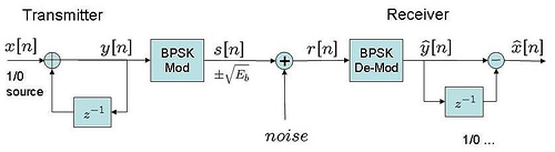
Typical transmit-receiver block diagram can be as follows:
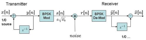
Figure: Transmit receive block diagram for coherent demodulation of DBPSK
The probability of error for a coherently detected, differentially encoded BPSK is given by (from Sec4.7.2 [DIG-COMM-SKLAR])
.
Notice that the bit error probability for coherent demodulation of DBPSK is typically double when compared to the bit error probability for coherent BPSK demodulation. This is because, due to differential encoding each decision error during coherent demodulation will cause two bits to be in error.
However, note that argument is not so straightforward for low SNR regions which I presume the reference [TEL-SYS-ENG-LINDSEY-SIMON] details about.
% Simple Matlab/Octave code for coherent demodulation of
% differentially encoded binary phase shift keying (DBPSK)
clear
N = 10^6 % number of bits or symbols
rand('state',100); % initializing the rand() function
randn('state',200); % initializing the randn() function
ip = rand(1,N)>0.5; % generating 0,1 with equal probability

ipD = mod(filter(1,[1 -1],ip),2); % %differential encoding y[n]=y[n-1]+x[n]
s = 2*ipD-1; % BPSK modulation 0 -> -1; 1 -> 0
n = 1/sqrt(2)*[randn(1,N) + j*randn(1,N)]; % white gaussian noise, 0dB variance

Eb_N0_dB = [-3:10]; % multiple Eb/N0 values
for ii = 1:length(Eb_N0_dB)
y = s + 10^(-Eb_N0_dB(ii)/20)*n; % additive white gaussian noise

ipDHat_coh = real(y) > 0; % coherent demodulation
ipHat_coh = mod(filter([1 -1],1,ipDHat_coh),2); %differential decoding
nErr_dbpsk_coh(ii) = size(find([ip - ipHat_coh]),2); % counting the number of errors
end
simBer_dbpsk_coh = nErr_dbpsk_coh/N;

theoryBer_dbpsk_coh = erfc(sqrt(10.^(Eb_N0_dB/10))).*(1 - 0.5*erfc(sqrt(10.^(Eb_N0_dB/10))));

close all
figure
semilogy(Eb_N0_dB,theoryBer_dbpsk_coh,'b.-');
hold on
semilogy(Eb_N0_dB,simBer_dbpsk_coh,'mx-');
axis([-2 10 10^-6 0.5])
grid on
legend('theory', 'simulation');
xlabel('Eb/No, dB')
ylabel('Bit Error Rate')
title('Bit error probability curve for coherent demodulation of DBPSK')
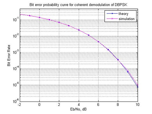
Figure: Bit error curve for coherent demodulation of DBPSK
Hope this helps.
Reference
[DIG-COMM-SKLAR] Digital Communications: Fundamentals and Applications (2nd Edition), Bernard Sklar
Dear Dr.Krishna;
Could you please help me to modulate DQPSK ?!
@rahman: Please check out the following post for non-coherent demodulation of DQPSK
https://dsplog.com/2010/04/12/non-coherent-demodulation-of-pi4-dqpsk-tetra/
Dear Dr Krishna,
thanks for your efforts .
I have a question which is not related to this topic.
my question is : DPSK can be demodulated using non-coherent detection .. How?
@Yaqoub: DPSK can be received using non-coherent receiver. Using only the relative phase change between consecutive symbols. However, if using non-coherent receiver, we will need around 3dB more snr to achieve the same bit error rate as a coherent receiver.
Wrong again Krishna.
See my post below.
@Iggy: I believe you referring to your comment (quoted again for completeness):
“What you described here is BPSK with differential encoding and decoding.
Real DBPSK is the same at Tx, but Rx side differs in the sense that the phases of two successive demodulated complex symbols (I/Q) are directly subtracted to get the output symbol estimate. i.e. x[n]= (real(y[n]*conj(y[n-1]))<0)
This works much better in the presence of significant phase drift and jitter."
How about the case when we use DBPSK when there is no phase drift/jitter?
I was expecting to see a 3dB difference between BPSK and DBPSK BER curves. This is not seen when I plot your DBPSK with a BPSK curve. Could you explain why this is the case?
@Krisha: I believe the 3dB gap comes out only if we use non-coherent demodulation for DBPSK. This post uses coherent demodulation.
I will have to work slowly to my question, so I beg your patience:
The third demod method (c) seems to refer to the OPTIMUM NON-COHERENT (or, as some authors define it, the optimum differentially coherent) dbpsk demodulation method (and its theoretical performance)
(a) and (b) requires phase tracking since thay can merely tolerate phase errors and can not tolerate any frequency errors (except for very short bursts)
(c) on the other hand, can tolerate a limited amount of frequency error and is not affected by phase errors at all. In (c) receiver produces a random phase copy of the carrier tone (not necessarily phase matched to received signal’s tone). Hence, it requires only a frequency estimator. Tracking is optional, and one can use a simpler tracker, with a first order loop filter without any cost, (whereas first order loop filtered tracker will cause phase bias and performance degradation in (a) and (b))
All these are fine, but I would like to compare the effect of Phase Jitter and/or the timing jitter of the ADC used in the receiver. (c) is not necessarily more immune to jitter than (a) and (b). Or is it?
There is also a fourth option, using a sub-optimum non-coherent receiver (as is defined in “Digital Modulation techniques” by Fuqin Xiong, Chapter 4.2) that does NOT produce a copy of the carrier tone (phase matched or otherwise). This receiver merely band pass filters the incoming IF (intermediate frequency) signal and multiplies with delayed version of itself, then integrates for the symbol period to get detector outputs. Theoretically, the cost in performance is about 1 dB.
My question is: How does the tolerance of this fourth option to ADC timing jitter, compares to other types of receivers? Does the fourth method have significantly more tolerance to jitter than (c) ? Does anyone have any experience on this type of system?
Best Regards
@B. Ahmet Dogrusoz: Sorry, I have not tried modeling the fourth approach which you listed above. Also, I have not studied the impact of ADC jitter on the BER performance.
is code rite ??? am not getting the graph as shown in figure 🙁
Dear Fahed,
after copy–> paste the code you should change the ‘ ‘ sign because it will not paseted in the correct shape.( i.e randn(’state’,200) ), and the all commas shall be changed
@Mohammad: Thanks 🙂
Alternatively, one can download the code and use it.
Can you provide some hints how to simulate DQPSK in fading Channel….I mean what are the changes need to be incorporated in your program
@Street Hawk: Well, in this simulation, you might want to introduce a multipath channel model and the corresponding equalizer at the receiver. You can refer to the post on BER for BPSK in ISI channel with zero forcing equalization.
https://dsplog.com/2009/11/29/ber-bpsk-isi-channel-zero-forcing-equalization/
hi krishna,
Please provide me the theoretical BER equation of DPSK over Rayleigh fading.
Regards,
@RAO: Sorry, I have not tried modeling that.
@Iggy: For completeness, may I summarize the error rates in AWGN alone for the three approaches:
(a) BPSK (normal) : 1/2*erfc(sqrt(Eb/No));
(b) DBPSK (coherent aka Differentially encoded BPSK) : ~= erfc(sqrt(Eb/No));
(c) DBPSK (noncoherent) : 1/2*exp(-Eb/No);
If we plot the curves, we can see that performance of (a) > (b) > (c). As you said, the difference is small though.
As I see, the advantage of using option (c) enables us to avoid a phase tracking circuit at the receiver (under the assumption that phase does not change too much from between two symbols). Reduction in complexity albeit with a (small) performance loss.
When you mentioned (c) outperforms (b), did you consider the presence of phase tracking circuit in the receiver for (b)?
Further, in the presence of frequency offset, which causes a linear change in phase, I would think that the performance of DBPSK (non-coherent) becomes shaky.
How do the receiver eye diagrams of (a) and (c) compare? I am familiar with eye diagrams in (a) but not (c). Does non-coherent (differential) demodulation result in a different eye diagram?
@David: Well, for plotting the eye diagram we need to run the scope in persistent mode and we need to know the phase also, right? So, am not quite sure whether the eye diagram will look different for (c).
I have to disagree:
Differentially Encoded BPSK (that you described) is close to BPSK itself for high E_b/N_0 (> 10 dB), but DBPSK (that I described) is less than 0.5 dB below.
http://en.wikipedia.org/wiki/Phase-shift_keying
If you include effects like significant phase jitter and phase drift (which is very common in real-life systems, especially if you have some spread spectrum modulation on top of (D)BPSK), then, DBPSK will outperform Differentially Encoded BPSK.
Can you provide some hints how to simulate DBPSK (noncoherent) in fading Channel….I mean what are the changes need to be incorporated in your program for noncoherent demodulation.
@Iggy: Yes, I agree.that the post describes coherent deomdulation of differential PSK. For differential demodulation, where one avoids phase tracking, one can use phase of y[n]*conj(y[n-1]) (as you suggested). However note that there is a 3dB penality in differential detection (when compared to coherent detection).
Can you provide some hints how your program would be suitably modified to simulate DBPSK (noncoherent) over fading channel….I mean what are the changes need to be done in your program to incorporate noncoherent demodulation.
@Street hawk: Firstly, you may try modeling in AWGN channel with non-coherent demodulation. For non-coherent demodulation, we need to look at two consecutive symbols, observe the phase growth and then use that information to demodulate.
With fading channel, I think we might need to have some equalization technique prior to demodulation (not sure).
What you described here is BPSK with differential encoding and decoding.
Real DBPSK is the same at Tx, but Rx side differs in the sense that the phases of two successive demodulated complex symbols (I/Q) are directly subtracted to get the output symbol estimate. i.e. x[n]= (real(y[n]*conj(y[n-1]))<0)
This works much better in the presence of significant phase drift and jitter.
Thank you
@Yahia:
It is called coherent, because the receiver need to align the phase prior to demodulation. Yes, as you correctly mentioned, this requires the receiver to do the frequency tracking.
Is it called coherent because it is mixed with a reference signal?
I know for DBPSK there are two demodulation schemes (coherent -optimal) and (noncoherent-suboptimal).
Does this scheme require a frequency tracking? to my understanding the answer is Yes but I would like to confirm that 🙂