My understanding of the CORDIC (Co-ordinate Rotation by DIgital Computer) thanks to the nice article in [DSPGURU-CORDIC].
The idea is that rotation of a complex number by an angle
can be achieved without using multipliers. The phase angle
is approximately equal to successive addition or subtraction of angles from a set of reference angles i.e.
, where
,
is the set of reference angles,
is the sign (takes +1 or -1) and
is the number of iteration.
Let the complex number corresponding to reference phase is
. The reference angles for different values of
is listed in the table below
| Re{Y} | Im{Y} = |
(in degrees) |
abs() | |
| 0 | 1 | 1.000000000 | 45.000000000 | 1.414213562 |
| 1 | 1 | 0.500000000 | 26.565051177 | 1.118033989 |
| 2 | 1 | 0.250000000 | 14.036243468 | 1.030776406 |
| 3 | 1 | 0.125000000 | 7.125016349 | 1.007782219 |
| 4 | 1 | 0.062500000 | 3.576334375 | 1.001951221 |
| 5 | 1 | 0.031250000 | 1.789910608 | 1.000488162 |
| 6 | 1 | 0.015625000 | 0.895173710 | 1.000122063 |
| 7 | 1 | 0.007812500 | 0.447614171 | 1.000030517 |
| 8 | 1 | 0.003906250 | 0.223810500 | 1.000007629 |
| 9 | 1 | 0.001953125 | 0.111905677 | 1.000001907 |
| …. |
Table: List of for
= 1 to 10
The set of operations for rotating a complex number by an angle
to generate
in the CORDIC way can be as shown below:
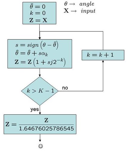
Figure: CORDIC for phase rotation
As the multiplication by involves only power of two, the operation can be implemented with out using ‘real’ multipliers. Nice advantage when we need to save hardware. The flip side is the number of iterations required for obtaining accurate estimate.
Additionally, the multiplication by introduces gain (as shown in the Table above) and after 16 iterations (
) the cumulative gain come to 1.64676025786545. Hence the block for compensating the gain.
% Simple Matlab example of phase rotation using CORDIC
clear
% creating the reference angles
Y_k = ones(32,1) + j*2.^(-1*[0:1:31])’; % values of Y
alpha_k = angle(Y_k)*180/pi; % reference angles
X = 2+3*j; % complex number to be phase rotated
thetaDeg = 25; % the phase to be rotated
K = 16; % number of iterations
thetaHat = 0; % initial phase angle
Z = X; % assigning the output as the input
% for different values of k
for k = 0: K-1
s = sign(thetaDeg – thetaHat); % difference
if s == 0 s = 1; end % to handle when thetaDeg = 0
Z = Z*[1 + s*j*2^(-1*k)];
thetaHat = thetaHat + s*alpha_k(k+1);
% dumping the variables for plot
sign_v(k+1) = s;
thetaHat_v(k+1) = thetaHat;
end
Z_ideal = X*exp(j*thetaDeg*pi/180);
Z_cordic = Z/1.64676025786545;
err = Z_ideal – Z_cordic;
errdB = 10*log10(err*err’)
close all
figure
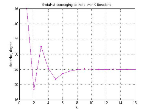
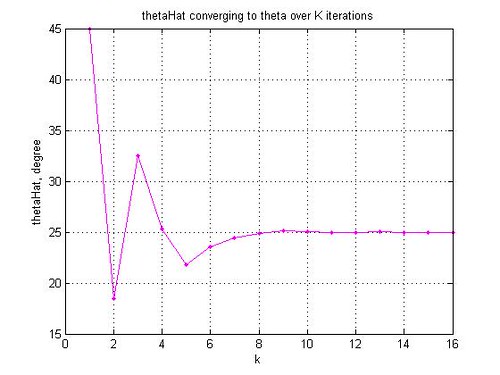
plot(thetaHat_v,’m.-‘)
grid on
xlabel(‘k’)
ylabel(‘thetaHat, degree’)
title(‘thetaHat converging to theta over K iterations’)
Reference
[DSPGURU-CORDIC] CORDIC FAQ in dspGuru(TM)
Hi,
How cumulative gain scaling is done in hardware?
Thanks
@sen: the scaling factor of 1/1.64676025786545 can be implemented as
octave:3> N=10; round(1/1.64676025786545*2^N)
ans = 622
i.e. multiply by 622 and round by 10bits.
If we want more precision, put higher values for N