 with transmit IQ gain/phase imbalance")
")
")
This is the third post in the series discussing receiver diversity in a wireless link. Receiver diversity is a form of space diversity, where there are multiple antennas at the receiver. The presence of receiver diversity poses an interesting problem – how do we use ‘effectively‘ the information from all the antennas to demodulate the data. In the previous posts, we discussed selection diversity and equal gain combining (EGC).
In this post, we will discuss Maximal Ratio Combining (MRC). For the discussion, we will assume that the channel is a flat fading Rayleigh multipath channel and the modulation is BPSK.
Background
We use the same constraints as defined in the Selection Diversity and Equal Gain Combining (EGC) post. Let me repeat the same.
1. We have N receive antennas and one transmit antenna.
2. The channel is flat fading – In simple terms, it means that the multipath channel has only one tap. So, the convolution operation reduces to a simple multiplication. For a more rigorous discussion on flat fading and frequency selective fading, may I urge you to review Chapter 15.3 Signal Time-Spreading from [DIGITAL COMMUNICATIONS: SKLAR]
3. The channel experienced by each receive antenna is randomly varying in time. For the receive antenna, each transmitted symbol gets multiplied by a randomly varying complex number
. As the channel under consideration is a Rayleigh channel, the real and imaginary parts of
are Gaussian distributed having mean
and variance
.
4. The channel experience by each receive antenna is independent from the channel experienced by other receive antennas.
5. On each receive antenna, the noise has the Gaussian probability density function with
with
and
.
The noise on each receive antenna is independent from the noise on the other receive antennas.
6. At each receive antenna, the channel is known at the receiver.
7. In the presence of channel , the instantaneous bit energy to noise ratio at
receive antenna is
. For notational convenience, let us define,
Maximal Ratio Combining (MRC)
On the receive antenna, the received signal is,
where
is the received symbol on the
receive antenna,
is the channel on the
receive antenna,
is the transmitted symbol and
is the noise on
receive antenna.
Expressing it in matrix form, the received signal is,
, where
is the received symbol from all the receive antenna
is the channel on all the receive antenna
is the transmitted symbol and
is the noise on all the receive antenna.
The equalized symbol is,
.
It is intuitive to note that the term,
i.e sum of the channel powers across all the receive antennas.
Note: The equations in the post refers the note on Receive diversity by Prof. RaviRaj Adve.
Effective Eb/No with Maximal Ratio Combining (MRC)
Earlier, we noted that in the presence of channel , the instantaneous bit energy to noise ratio at
receive antenna is
.
Given that we are equalizing the channel with , with the
receive antenna case, the effective bit energy to noise ratio is,
.
Effective bit energy to noise ratio in a N receive antenna case is N times the bit energy to noise ratio for single antenna case. Recall, this gain is same as the improvement which we got in Receive diversity for AWGN case 🙂
Click here to download Matlab/Octave script for plotting effective SNR with Maximal Ratio Combining in Rayleigh channel

Figure: Effective SNR with Maximal Ratio Combining in Rayleigh fading channel
Error rate with Maximal Ratio Combining (MRC)
From the discussion on chi-square random variable, we know that, if is a Rayleigh distributed random variable, then
is a chi-squared random variable with two degrees of freedom. The pdf of
is
.
Since the effective bit energy to noise ratio is the sum of
such random variables, the pdf of
is a chi-square random variable with
degrees of freedom. The pdf of
is,
.
If you recall, in the post on BER computation in AWGN, with bit energy to noise ratio of , the bit error rate for BPSK in AWGN is derived as
.
Given that the effective bit energy to noise ratio with maximal ratio combining is, the total bit error rate is the integral of the conditional BER integrated over all possible values of
.
.
This equation reduces to
, where
.
Refer Equation 11.12 and Equation 11.13 in Section 11.3.1 Performance with Maximal Ratio Combining in [DIG-COMM-BARRY-LEE-MESSERSCHMITT]. Again, I do not know the proof 🙁
BER Simulation Model
The Matlab/Octave script performs the following
(a) Generate random binary sequence of +1’s and -1’s.
(b) Multiply the symbols with the channel and then add white Gaussian noise.
(c) Chose that receive path, equalize the received symbols per maximal ratio combining
(d) Perform hard decision decoding and count the bit errors
(e) Repeat for multiple values of and plot the simulation and theoretical results.
Click here to download Matlab/Octave script for simulating BER for BPSK in Rayleigh channel with Maximal Ratio Combining

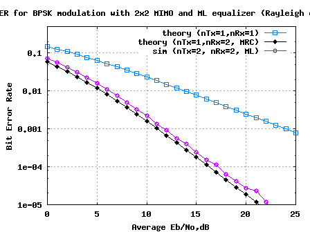
Figure: BER plot for BPSK in Rayleigh channel with Maximal Ratio Combining
Reference
[DIG-COMM-BARRY-LEE-MESSERSCHMITT] Digital Communication: Third Edition, by John R. Barry, Edward A. Lee, David G. Messerschmitt
Dear Sankar,
The ber formula can be solved with the aid of [R1, eq. (5A.2)].
[R1] M. K. Simon and M.-S. Alouini, Digital Communication over Fading Channels—A Unified Approach to Performance Analysis
@yangakai: Thanks. Will take a look
Sir,
yours website is very useful.Thank you so much.
Hi, Thanks a lot for the code..i have a doubt..if you keep increasing the no. of antennas, the BER curve should tend towards the AWGN BER of BPSK right…but in this case…i observed..say we have 5 antennas,the curve is becoming less the AWGN BER of BPSK curve..please explain..
@Shruti: Yes, as you said more the number of receive antennas, the ber curve will tend towards the AWGN BPSK BER.
When you simulated, did you have a non-unity gain for the channel?
Thanks for your reply,sir,
i just tried modifying the existing code just by increasing the no. of receivers.
how do i model non-unity gain? please explain this concept.
Thanks a lot 🙂
is it okay if the curves(Rx>5) as we increase the antennas become smaller than the AWGN curve? What is its physical meaning?
@Shruti: Hmm… it should not be better than AWGN
is it okay BER curves for Rx>6 become smaller than the AWGN curve? What is its physical meaning?
@Shruti: Well, I do not think it should be better than AWGN
@Shruti: The gain is caused by the channel term h in u = x*h + n.
Make sure that over many realizations, the E(|h|^2} = 1 for unity gain
I have the same code. but just added more receivers, and taken
h = 1/sqrt(2)*[randn(nRx(jj),N) + j*randn(nRx(jj),N)]
as you have taken.
How do I change this expression so as to get unity gain?
@Shruti: Hmm… i see your point. Try
h = 1/sqrt(2)*1/sqrt(nRx(jj))*[randn(nRx(jj),N) + j*randn(nRx(jj),N)]
Dear Krishna
your webpage is very useful for me
thank you
How is this different from Equal Gain Combining (EGC) scheme ??
The output SNR of EGC is the sum of the SNRs on all brances. Also, as Prof. RaviRaj Adve mentioned in his note on Receive Diversity that for Maximal Ratio Combining, “The output SNR is, therefore, the sum of the SNR at each element.” (Just next to eq. 26, page 7)
I’d really appreciate if you can clear out my confusion.
@Humayun: In equal gain combining, all the received copies of the signal are used with the same weight. However, in maximal ratio combining, the received copy with lower strength is given lower weightage.
Helps?
Hi Krishna,
Thanks for this article and the code. It is very useful. I have a minor question. When you generate the Rayleigh channel are you considering those samples to be frequency domain responses of the channel?
@AncientGlory: Am considering them as realizations of a flat fading channel.
hello Krishna,
please help me.i need to know if this post on MRC is for GSM or CDMA system.thanks.
@Arinze: This post discuss the general concept – not specific to GSM or CDMA system
Hello Krishna,
thanks for this wonderful post on MRC. please is this code for GSM or CDMA system?
thanks.
Sir , I want to know the algorithm that you have used for Matlab/Octave script for plotting effective SNR with Maximal Ratio Combining in Rayleigh channel AS THAT OF BER MODEL. PLEASE ! Tell me which code represents MRC and which for RAYLEIGH CHANNNEL ., variable jj & ii what represents . please help me to know
sir .Please!!!
@Taiyyab: The algorithm is to multiply by conjugate of the channel h. The term ii is for power levels Eb/N0 and jj is for the number of receive antennas
Hi krishna,
Your codes are really useful. But I donot understand why the “effective SNR ” is
EbN0EffSim(ii,jj) = mean(abs(yHat)) given in the “script_maximal_ratio_combining_effective_snr.m”
Thanks~
@HugoWong: yHat = conj(h)*y which captures the post equalization signal to noise ratio
Thank you. Can you help me with the codes of a relay using Amplify and forward (AAF) protocol.
@Gopu: Have not studied that topic
Hi krishna,
Can you please send me the codes of a Rayleigh fading channel
@Gopu: Please take a look at
https://dsplog.com/2008/08/10/ber-bpsk-rayleigh-channel/
https://dsplog.com/2008/08/26/ofdm-rayleigh-channel-ber-bpsk/
In general, you can take a look at https://dsplog.com/tag/rayleigh/
Hi krishna,
Have you done any work on cooperative diversity in wireless communication especially using a relay (Decode and forward,amplify and forward) and a mrc combiner ? If yes, can you please send me the codes.
@Gopu: Hmm… no. Sorry
How can I change it for MRC for QPSK. Does the curve change for QPSK case? Please help me with the codes.
@Rabi: Yes, the curve should change
Hi krishna,
Your codes are really useful. Have you done any work MIMO for LTE ?? especially spatial multiplexing? If yes, can you send me the codes.
Thank you.
@Sooraj: No, have not studies LTE
Hi Krishna,
how should i simulate SINR for cooperative MIMO scheme(considering interference from other cells).The SINR equation is given below
SINR =
( |h11 |2 + |h12|2 ) E{x12} /
σ2 + ∑ k=312 |h1k|2 E {xi2}
my input is in terms of packets.
please help me.
@Jayashree: I have not tried simulating cooperative mimo schemes
Hey,
Thank you so much for the wonderful work. It helped me a lot to start using Matlab for my work in wireless communications.
Do you have any article written on Coordinated Multipoint or Base Station Cooperation? Can you also give me a good reference to better understand MRC?
I have another question about your post. You have mentioned in the post that
“Given that we are equalizing the channel with h^H ”
Where h^H means the Hermitian transpose. But we are equlizing the channel with h+. Which is the pseusdo inverse of h. Aren’t we??
@Raj: Replies:
1/ Thanks.
2/ No, nothing on Coordinated Multipoint
3/ Digital Communication: Third Edition, by John R. Barry, Edward A. Lee, David G. Messerschmitt is a good reference
4/ Well, guess both are same. Agree?
how i read the book for free? i’m only student… and i don’t have money to buy it…. please helpme to read the book…^_^!
@dedy: emailed you the instructions
Hi Mr. Khrisna, can you show me why there is a negative sign in front of
-Eb_N0_dB(ii) in this code y = h.*sD + 10^(-Eb_N0_dB(ii)/20)*n;
Thanks so much.
@tu_winner: The -ve sign to scale the noise voltage for attaining the given Eb/N0
hi.. what can we do for more antennas ?? how can we simulate this
I change the code but not clearly true
nRx = [1 2 4];
theoryBer_nRx1 = 0.5.*(1-1*(1+1./EbN0Lin).^(-0.5));
p2 = 1/2 – 1/2*(1+1./EbN0Lin).^(-1/2);
theoryBer_nRx2 = p2.^2.*(1+2*(1-p2));
p3 = 1/2 – 1/2*(1+1./EbN0Lin).^(-1/2);
theoryBer_nRx3 = p3.^3.*(1+3*(1-p3));
close all
figure
semilogy(Eb_N0_dB,theoryBer_nRx1,’bp-‘,’LineWidth’,2);
hold on
semilogy(Eb_N0_dB,simBer(1,:),’mo-‘,’LineWidth’,2);
semilogy(Eb_N0_dB,theoryBer_nRx2,’rd-‘,’LineWidth’,2);
semilogy(Eb_N0_dB,simBer(2,:),’ks-‘,’LineWidth’,2);
semilogy(Eb_N0_dB,theoryBer_nRx3,’gd-‘,’LineWidth’,2);
semilogy(Eb_N0_dB,simBer(3,:),’ks-‘,’LineWidth’,2);
axis([0 35 10^-5 0.5])
grid on
legend(‘L=1 (theory)’, ‘L=1 (sim)’, ‘L=2 (theory)’, ‘L=2 (sim)’,’L=3 (theory)’, ‘L=3 (sim)’);
xlabel(‘Eb/No(dB)’);
ylabel(‘Bit Error Rate’);
title(‘BPSK modülasyonu Maximal Ratio Combining (Rayleigh channel) için BER’);
@tuncay: The code change looks okay. I did not verify the theoretical equation though. What’s the issue which you are observing?
I think my theorical equation is not valid.do you know true formula ..if you debug this code you can understand me I want to triple curve
@tuncay: For the theoretical equation, did you refer Equation 11.12 and Equation 11.13 in Section 11.3.1 Performance with Maximal Ratio Combining in Digital Communication: Third Edition, by John R. Barry, Edward A. Lee, David G. Messerschmitt
thank you for your intrest
hi.. what can we do more antennas ?? how can we simulate
@tuncay: Did you mean what can we do with more antennas?
hi Krishna, I am Pranjal from Guwahati. I have a question for you’ in MRC how can i use DPLL(digital phase lock loop) before decision ckt
@Pranjal:Why do you wish to use a digital PLL. To handle frequency errors?
hi krishni!thanks so so so so … very much for leading codes!:D
Hi Krishna, I am using 12 antennas with 30 degree spacing in a full circle. Each antenna has a 90 degree 3 db beam width , therefore I have 1080 degrees of coverage in a 360 degree circle (lots of overlap). I found by experimentation that I realized combining gain with this arrangement. I am using maximum ratio combining and the results are amazing. I did this on a hunch and really was surprised by the result. Each antenna had 15 db gain and most of the time I had 3 antennas with some signal all the time! I realized below threshold demodulation when this happened! How can I calculate “combining gain”!?
Thanks!
@Jim: Well, I did not quite understand the setup. Its 12 antennas for transmitter or receiver or split? How did you measure the gains.
Also, if the receiver received two signals from a cooperative path and a direct path, how to combine these two signals using MRC and how to find the overall bit bpsk error probability?
my best regards
Adem
Hi Krishna,
This is my first time to deal with a Rayleigh fading channel. could you clarify for me the meaning of hi and how to find it using a numerical example?
In a wireless cooperative scheme in which the node that’s in between the receiver and the transmitter recieves the transmitted BPSK signal and amlify it and forward it to the receiver. How to find the overall BPSK bit error probability (in the case of a Rayleigh channel?
Hello Mr. Khrisna, I’m very thankful for ur explanation ’bout this topic…
may I ask ’bout ur code:
y = h.*s + 10^(-Eb_N0_dB(ii)/20)*n;
-Why the rayleigh channel (h) multiplied with signal(s)…can I change the .* with ‘conv’?
-And is AWGN noise and multipath channel always complex value?can I just change them, so it just only hav the real part (without imajiner value)?
-and my last question: what should i do with AWGN & rayleigh ch codes and another codes if I change the data(BPSK) into 2D matrix (e.g. 3×10^6)?
sorry for my terrible english…thanks again…
my rgrds,
Phill
@Phill: My replies
a) Yes, you may change .* to conv. I use .* as the channel is a single tap (flat fading) hence .* is equivalent to conv.
b) Well, per the model both are complex values (i.e. it affects transmission on sine and cosine transmissions). For you trial, you may try to play with it
c) Well, you might want to make h and awgn from vectors to matrices.
Your english is good.
Hello Krishna,
I wanted to ask you, is this the same as a ‘RAKE’ receiver in CDMA?
Thanks,
@Talib: I would think so. We have multiple copies of the transmitted symbol and we want to combine them optimally.
Hi,
I got a bit confused. Are ZF and MRC the same?
Thank you.
@aydar: Well,
a) ZF tries to address the problem where there is interfernce from an undesired waveform and we try to force that to zero.
b) MRC tries to optimally combine two copies of the same information so as to result in minimal BER.
Thank you for the reply,
MRC maximizes received SNR after antenna combining. I think, so does ZF in SIMO case too (when ithere is no inter-cell interference), in MIMO it tries to supress interferering MIMO user/stream => maximizes SINR. So, my question is can you write me a formula of MRC for MIMO case or is MRC defined only for SIMO?
Thank you in advance Krishna.
@aydar: I agree with your comment. Sorry, I do not have the precise equation for MRC in MIMO case where there is interference.
Hi,
do you know any relation between the snr of the received signal and the BER.
In my case, using MREC i manage to get the same snr of MRC , however still the bit error rate of MREC is 0.5, therefore i think if there is a relation between BER and snr i could find the source of the problem..
regards,
@blwf: For different modulation types and based on the channel model, there exists a relation between BER and SNR. For eg,
for BPSK in AWGN channel, BER = 1/2erfc(sqrt(Eb/N0)) and so on…
For solving your 0.5 BER problem, I would suggest you to try with no noise, unity channel etc and work towards identifying the bug. Good luck.
Hi krishna,
you mentioned in one of your earlier replies that the equalizer is xHat = (h’*h)^{-1}*h’y where ()’ is the conjugate transpose.
So does the above equation correspond to the following in your code?
% equalization maximal ratio combining
yHat = sum(conj(h).*y,1)./sum(h.*conj(h),1);
I assume u used xhat and yhat interchange? Thank you.
@eric: Yes, that code snippet which you pasted corresponds to the equalization part.
hi krishna,
for the statement
y = h.*sD + 10^(-Eb_N0_dB(ii)/20)*n;
can i verify that the -Eb_N0_dB(ii)/20 is the weight factor?
why is there a negative sign in front of -Eb_N0_dB(ii). And why we divided it by 20, not 10? Thanks!
@eric: My replies
1/ We are scaling the noise voltage for simulating the effect of various Eb/N0 values.
2/ I defined Eb/N0 as the ratio between signal power and noise power. Given that the signal power is unity, I scaled the noise voltage to achieve the given Eb/N0 value. Division by 20 happens because we are dealing with voltage signals and not power.
thanks for the program.
1. but dont you think you should add average BER ?
because if the channel was not fast fading (changing with every samply-symbol-) you will not get the same performance(already tried it)
2. Do you know any way helps to apply the MREC using the channel auto correlation matrix. whenever i want to apply it i get inconvenient results.
please help/
regards
@blwf: My replies:
1/ Am assuming that the channel is fast fading
2/ What is MREC ?
It is maximum ration eigen combining. using the eignevectors of the received signal as weights?
@blwf: Hmmm, am not familiar with that approach.
Why we are taking normalized signal energy equal to 1 while doing simulation? Why not actual signal energy in some joule?
@Street hawk: In simulations our objective is to characterize the performance in comparison with other types of algorithms. Hence it makes sense to normalize the transmit power to 1 for all of our simulations to allow a fair comparison.
Hi Krishna
I am working with Weibull channel.but the base to this is Rayleigh channel.
Weibull channel envelope can be obtain from Rayleigh envelope.
I was doubtful whether i can use these Diversity techniques for Weibull channel?
Regards,
Neetu
@Neetu: Though I have not tried modeling Weibull channel, I guess you can try these diversity techniques to see the performance gains, if any.
hello krishna pillai
i am doing M.Tech project in cooperative communication in MIMO cellular networks, i don’t know how to start write matlab code for cooperative communication in mimo cellular networks. pls help me.
with regards
karan
@karan: Sorry, I have not tried modeling co-operative communication networks.
Hi Krishna,
Can you describe the velocity effect on the communication channel such as BER vs Ebn0 with varying the velocity in doppler frequency ?
I want to simulation it in matlab.
Thank you very much.
@J_tce: Till now, most of the simulation assume that the channel experienced by each symbol is independent. I have not yet discussed Doppler frequency till date. Will add to my to-do list.
thanks your mrc code is exellent i learned a lot from it.
@Khattak: Good, glad to hear that 🙂
hi
how can i write a code to plot BER with SNR for the theoritical result of MRC with L number of idepentent paths?
thank you
@Yazeed: You may use the equation for BER which is provided towards the end of the post. That is for N received antenna case.
hellow Mr Krishna
can you hel me to creat BER for QPSK with rain attenuation in matlab
@wayan: I am not familiar with modeling rain attenuation. However, I have written a post on symbol error rate for QPSK in AWGN
https://dsplog.com/2007/11/06/symbol-error-rate-for-4-qam/
Hope this helps.
hi,
i mean when you make sum. to all snr from branches we assume that there are no correlation can you help me if there are correlation ?
thanks
@leth: I have not tried modeling systems where there is correlation between the channel seen by each antenna.
@leth: just define the covariance matrix according to your problem using the correlation coefficient formula,then use mvrnd(MU,SIGMA) function to form columns of random variables and then separate them to use…
i am still wait
i hope you can help me
hi all,
in the simulation of MRC, it depend that the branches are i.i.d can you send me matlab code for MRC with correlated branch.
i need it ASAP.
thanks
@leth: Sorry, I have not tried modeling scenarios where there is correlation between the channel observed at both the antennas.
respected sir,
I have seen your code for BER for BPSK in Rayleigh channel with Maximal Ratio Combining and i want to inplement this in ofdm system can you help me what should be my approach.
Thanks
@sahil: If I may pust simplistically,
a) in the transmitter group bits and allocate them to each OFDM symbol, take ifft add cyclic prefix and send.
b) in the receiver, as we have two receive paths, take fft of OFDM symbol from each path, and then apply maximal ratio combining on the signal at the output of fft.
Hope the post on BER for BPSK with OFDM modulation https://dsplog.com/2008/06/10/ofdm-bpsk-bit-error/ will be of help.
I hope you can help me with this matlab code:
Consider QPSK transmission over flat fading Rayleigh channels and the following three systems: i) 1×1 system , ii) 1×2 system employing maximum ratio combining (MRC), and iii) 1×2 system (two transmit antenna and a receive antenna) employing Alamouti space-time coding. The channels in the last two systems are assumed to have the same variance and the noise samples are assumed to be uncorrelated and circularly symmetric Gaussian variables with the same variance.
Let p denote the correlation between the receive (transmit) antennas for the 1×2 (2×1) system. Estimates the average (over the channels) bit error rate (BER) for the three systems for different values of the average signal-to-noise ratio (SNR).
@ R@y: I have not tried simulating the BER in the case where channel is correlated. For posts on alamouti STBC, you may refer to http://www.dsplog.com/tag/alamouti.
Good luck.
Hi
Me too i am interested in this question, is it possible to change MRC code by considering a constant nRx?
@Maha: Yes, indeed. Just change nRx variable accordingly.
Perfect! thank you that was really helpful, before i visit your website i was little bit confused in using MRC EGC SC but it’s more clear right now.
Concerning your MRC code, i was trying to consider a constant number of receiver channels ‘nRx=4’ by removing the variable ‘jj’, but the system displays this error message:
‘Warning: Input arguments must be scalar.’
i was wondering how could to avoid this problem, and is there any other variable that we have to change in order to have a constant nRx?
@Mathieu: I just checked. To simulate 4 receive chains, just change nRx = [1 2]; to nRx = [4]; Just make sure that the calls to simBer variable in the plots are modified.
Hi Krishna
I have a question about your MRC code 🙂
Could please give us more details about this section :
” % counting the errors
nErr(jj,ii) = size(find([ip- ipHat]),2); ”
i don’t see why did you use the function “find”?
Thank you in advance 🙂
@Mathieu: find() gives the index of non-zero elements in the error vector [ip – ipHat]. And then size() gives the number of non-zero elements -> which is equal to number of erraneous bits.
hi
I trying to learn multiuser detection techniques for CDMA and OFDM. I’m a beginner so do you have any advice for me?
Are you planning to post tutorials regarding that subject?
I’m a real rookie so tell me about some resource thats starts off at the basic, not the book of Verdu!! please
@commengr: The multi user detection is a close cousin of problem of MIMO demodulation. In MIMO, the interference is caoused by transmission in spatial dimension (read other antenna in the same devide); in multi user scenario, the interference is caused by other users.
You may look at the posts on receiver structures for MIMO @ https://dsplog.com/tag/mimo
Hope this helps.
thanx for ur reponse to my previous post i am trying to RAKE
hi krishna
tell me in the case of transmit diversity
can we use MRC at the receiver???
and do we use combiner before equalizer or after that
regards
sara
@sara: Well, it depends on the transmit diversity scheme employed. Hopefully, the attached link on 2 transmit, 1 receive alamouti STBC should give your pointers
https://dsplog.com/2008/10/16/alamouti-stbc/
hello..
i have derieved average probilty of error of bpsk in nakagami fading by using moment generating function.now i need to get the formula in presence of mrc diversity.how can i do so ?
@rahul: Sorry, I am not familiar with derivations. Good luck. Just in case: if you wish to publish your results from the derivations in dsplog.com, please do mail me.
hi krishna!
nice job!!!!
well done!!!
i want to combine two signals at the receivers that are comming from different paths(i-e a multipath enviornment) where second signal is being received at the reciver with a delay of about 3 to 4 symbols.(currently i am using EGC)
now what i am getting at the receiver is very high BER, even though i am using rrc filter and DFE equalizer. can u plz suggest me how to address this problem.
also suggest me some good combining and equalization techniques for this problem!
waiting for ur response
regards
sara
@sara: Delay of 3 to 4 symbols! Quite high, aint it?
Anyhow, if you know the delays, you may add a rake receiver (to collect energy from all the delay elements and make them add coherently) to improve the BER. This may improve your receiver’s latency. But, should not matter in your simulatins where you want to prove your algorithm. Hope this helps.
hi krishna….
i want simulation of ofdm without noise…
plz can u help me…
regards
maria
@maria: Please look at https://dsplog.com/2008/02/03/understanding-an-ofdm-transmission/
Hi Krishna,
Nice derivation. For mathematical clarity, it is appropriate to replace Eb/No, in the last equaiton, by the average SNR (which can be different from Eb/No in the case where E[|h_i|^2] is different from 1.
@Sintat: Thanks for the comment. I agree. However, as this example is pertinent to flat fading Rayleigh channel with E[|h_i|^2] = 1, may I just continue using Eb/No. Thanks.
dear sir,
1) can you tell me what mean of nRx = [1, 2]?
2) n = 1/sqrt(2)*[randn(nRx(jj),N) + j*randn(nRx(jj),N)]
can you explain the element of randn(nRx(jj), N)?
3) yHat = sum(conj(h).*y,1)./sum(h.*conj(h),1)
is it possible to modify to become h*d^-2 and repeat it to cal. the error prob.?
@Martin:
(1) nRx = 1, showed results with flat fading with only one receive chain. nRx = 2 showed results with 2 receive chains using MRC. Both were provided to facilitate an easy comparison.
(2) randn() generates gaussian random variable with mean 0 and variance 1.
(3) In general,there can be multiple coding styles to reach the same result. What I chose need not be the way you chose.
Can I use this program to produce a 1*m rayleigh fading? 1 is transmitter m is receivers
please help, thanks
@davis: I have not tried modeling spatial correlation. However, from a quick googling, came up with the following
page:
Simulation of the Spatial Covariance Matrix
http://users.ece.utexas.edu/~rheath/papers/2003/multi_mode/index.htm
Further, may I suggest that you are mixing two things. The doppler frequency corresponds to correlation in time. The antenna spacing results in spatial correlation. I recall reading that 0.5 wavelength spacing should results in spatially uncorrelated channels.
If I would want to simulate the MRC with corelation in indoor environment, how chould you suggest to make the two rx to be dependent on the distanse of the antennas?
i read that the 0.48wavelength they chould be uncorellated because of dopler frequency, but in indoor where the RX are static is there any dopler effect and can I get uncorelated chanels?
@davis: Yes, you are correct. In the article and simulations, no correlation between the channels was assumed.
Whether this is a valid assumption depends on the channel model and antenna spacing. For eg, if the antennas are far apart, then each antenna seeing an independent channel is highly probable. I would expect typical multi-antenna systems to provide enough spacing (more than half wavelength) between antennas to reap the benefits from diversity.
Thank you for you replay
I see that in your code there is no corelation between the two 2 chanels ,Is it correct to do that?
@davis : Well, since I have not studied the topic, I cannot comment on absolute terms. However, given than BFSK has 3dB poorer results than BPSK in AWGN, I would think that you should obtain comparable results.
May I recommend to proceed as follows:
(a) Make 1×1 BFSK simulation in a single tap Rayleigh channel. I would think that you should obtain a curve which is 3dB poorer than the corresponding BPSK case.
(b) Once you have obtained that, then you may move to 1×2 case. With 1×2 case, am guessing that you should see the improvement as seen for BPSK case (around 15dB lower BER at 10^-4 point).
Hope this helps. Please do report your findings. All the best.
@nihmot: You can find posts discussing symbol error rate an BER for typical QAM modulation schemes in AWGN here.
URI: https://dsplog.com/tag/qam/
I hope it will be reasonably easy for you to adapt the concepts and write a simulation model to suit your requirements
@ila: Sorry for the delayed response, I was down the viral fever.
To answer all your queries
(Q1) can u pls kindly explain why do we use this?
sD = kron(ones(nRx(jj),1),s);
[Ans1] This is to repeat the same transmit symbol to be received by nRx receive antennas. For eg,
lets say s = [1 2 3 4 5];
kron(ones(3,1),s) = [1 2 3 4 5;
1 2 3 4 5;
1 2 3 4 5]
(Q2) Do you consider the weight in the code?
[Ans2]Yes, this is taken care. For eg, consider channel h = [1;2];
pinv(h) = 1/(5)[ 1 2].
For equalization, we multiply pinv(h) with received [y1;y2]. We can see that y2 is given more weightage than y1 during equalization.
Does this help?
i’m using MRC in hoyt channel, so my code is slight different…i just want to ask that the weight that we multiply with the received signal is h’/h*h’ or h’/N
where h is channel and N is noise power…
i’m just confused about how to take the weights…
pls do reply soon…
@himanshu: I have not tried modeling hoyt fading channel. However, in the current post, the weighting factor was formed as follows:
Assume
y – [nrx x 1] received vector
h – [nrx x 1] channel vector
x – [1 x 1] transmit symbol
n – [nrx x 1] noise vector
y = hx + n
The equalizer is
xHat = (h’*h)^{-1}*h’y where
()’ is the conjugate transpose.
hi Krishna
i am doing project on BER with bfsk on rayleigh channek also using MRC and i get better performans with 2 reicevers instead of one more than 3db in some case i got 8db better
is this posible? what is the maximum improvement should I expect?
THANKS
hi love this but am working on BER performance with 4-,8-,16-QAM over flat rayleigh fading channel using MRC tachnique. need a simulation code !!! can anyone help here….
Also, in Wiki, it’s stated: http://en.wikipedia.org/wiki/Diversity_combining
“MRC: The received signals are weighted with respect to their SNR and then summed”.
do you consider the weight in the code?
hi krishna,
can u pls kindly explain why do we use this?
sD = kron(ones(nRx(jj),1),s);
hi Krishna,
thanks for the great posts u have put on. very helpful! 😉
i dont really understand the part where:
sD = kron(ones(nRx(jj),1),s);
why do we do this?
i read in Wiki “The received signals are weighted with respect to their SNR and then summed”
http://en.wikipedia.org/wiki/Diversity_combining
i cant find where the calculation of weight in the code? is there assumptions made that this can be ignored?
thanks & look fwd to your kind reply
@farie: I recently wrote a post on BER simulation of BPSK in Rayleigh channel with 2Tx, 1Rx antenna Alamouti STBC coding.
URI: https://dsplog.com/2008/10/16/alamouti-stbc/
Hope this helps.
I was just browsing through your posts and wanted to know if you have a code for simulating BER for BPSK/QPSK/16QAM in Rayleigh channel with Alamouti code of 2×1 and 2×2 (two transmit one receiver and two transmit and two receivers).
@Michael: Firstly, sorry for the delayed response. I was away from my blog desk for while.
Yes, you are right and captured a typo. It should have been (N-1+k) chose k rather than (m-1+k) chose k. I corrected the equation in the post. Thanks again.
First of all, very nice post!
I’ve got one question. In your bit error calculation for mrc you say you calculate the sum of (m-1+k) over k. What is m and where does it come from?