 with transmit IQ gain/phase imbalance")
")
")
In two previous posts, we have derived theoretical symbol error rate for 16-QAM and 16-PSK modulation schemes. The links are:
(a) Symbol error rate for 16-PSK
(b) Symbol error rate for 16-QAM
Given that we are transmitting the same number of constellation points in both 16-PSK and 16-QAM, let us try to understand the better modulation scheme among the two, i.e. to answer the following question:
For the same signal to noise ratio , will 16-PSK or 16-QAM give a lower symbol error rate?
Distance between the constellation points for 16-PSK
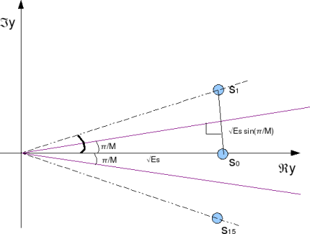
Figure: Distance between constellation points for 16-PSK modulation
As can be seen from the above figure, the distance between symbols and
can be approximated as,
, where
.
Distance between the constellation points for 16-QAM
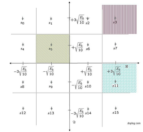
Figure: Distance between constellation points for 16-QAM modulation
As can be seen from the above figure, the distance between the constellation points for 16QAM modulation is,
.
Comparing both,
.
The distance between the constellation points fo 16QAM modulation is around 1.6x the value for 16PSK modulation. Expressing in dB’s, this comes to around .
More the distance between the constellation, lesser is the chance of a constellation point getting decoded incorrectly. This implies that for the same symbol error rate, 16QAM modulation requires only 4.19dB lesser signal to noise ratio , when compared with 16PSK modulation.
% Matlab/Octave code for comparing the symbol error rate for 16PSK and 16QAM modulation

clear

M = 16;

Es_N0_dB  = [0:25]; % multiple Es/N0 values

theorySer_16PSK = erfc(sqrt(10.^(Es_N0_dB/10))*sin(pi/M));

theorySer_16QAM = 3/2*erfc(sqrt(0.1*(10.^(Es_N0_dB/10))));

close all

figure

semilogy(Es_N0_dB,theorySer_16PSK,'bs-','LineWidth',2);

hold on

semilogy(Es_N0_dB,theorySer_16QAM,'mx-','LineWidth',2);

axis([0 25 10^-5 1])

grid on

legend('theory-16PSK', 'theory-16QAM');

xlabel('Es/No, dB')

ylabel('Symbol Error Rate')

title('Symbol error probability curve for 16-PSK and 16-QAM modulation')
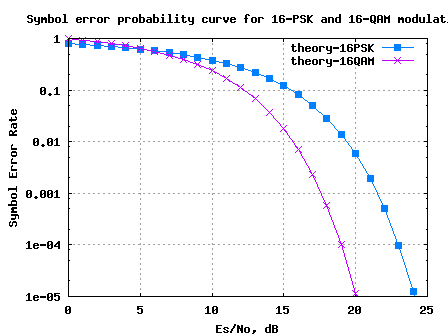
Figure: Symbol Error Rate for 16PSK and 16QAM modulation
As can be observed, at a symbol error rate of , 16QAM requires only arond 19dB whereas 16PSK requires around 23dB of
.
No wonder we find 16-QAM modulation instead of 16-PSK in typical specifications like IEEE-802.11a, IEEE802.16d etc. 🙂
Hope this helps.
Thanks,
Krishna
Any one got the MATLAB code to simulate cooperative communication using R-S codes? Please I need it for my research.
Thanks
@oluseye:Reed Solomon code-decoding is one of the TODO’s. However, you can find some posts on Hamming decoder and Viterbi decoder at
https://dsplog.com/category/coding/
Hi i am working on 16 QAM transmitter using DSP my section is to simulate it using matlab i am not using existing function for modulate and demodulate i built it by myself and i use RRC in my code but what i really want to know is the relationship between distance (between adjacent symbols) and the energy per bit Eb please give me the equations please
@dema: Given that each symbol carriers k = log2(M) bits, where M is the modulation size
Es/N0 = k*Eb/N0
https://dsplog.com/2008/06/05/16qam-bit-error-gray-mapping/
@irshad. Contact me at mrniceshah@yahoo.com. and i will give you the code.
i need 8psk matlab code in Rayleigh channel.
@irshad:I do not have any direct simulations handy, but I would assume it is simple for you to adapt
https://dsplog.com/2008/03/18/symbol-error-rate-for-16psk/ and
https://dsplog.com/2008/08/10/ber-bpsk-rayleigh-channel/
just change M=16 into M=8, correct me if i am wrong….
dear sir..
please help me,,
I am a EEPIS college student who was working on the final task of power control for rain attenuation … I’m confused with the usage for m-PSK tresshold what is the value of SNR tresshol for example 16 PSK, and from which the empirical calculation?
@eca: How do you set the threshold? Is it based on BER constraint?
dear sir \
can you tell me ……………comparison 16QAM and 64 QAM with respect to bandwidth and power requirement
@R B Patil: Please refer to the post on https://dsplog.com/2008/07/08/compare-bpsk-qpsk-4pam-16qam-16psk-64qam-32psk/
Hi krishan sankar
I work Qouds university, please send me your simulation code for pre-fft and post fft at frequency selective fading and comparison pre fft and post fft
in ofdm .
thank a lot
@waleed salos: Hopefully the post on BER for BPSK with OFDM in multipath channel might be of help
https://dsplog.com/2008/08/26/ofdm-rayleigh-channel-ber-bpsk/
Hi Krishna,
I wanna thanku inadvance for great articles you’ve done and I wonder if you could compare the bit error probabilities of the 64-QAM nd a 64-PSK? Also, i’d be greatful if you have any matlab scripts for comparing.
@BusyWasp: Please check the posts
https://dsplog.com/2008/07/08/compare-bpsk-qpsk-4pam-16qam-16psk-64qam-32psk/
http://www.dspdesignline.com/howto/208801783;jsessionid=KQBZX4ZJRFCX0QSNDLRSKHSCJUNN2JVN?pgno=1
I have discussed the M-QAM case, which you can adapt to 64-QAM.
The post and code in 16-PSK is also discussing M-PSK case.
https://dsplog.com/2008/03/18/symbol-error-rate-for-16psk/
Good luck.
Hi Krishna, when use normalization the system performance get worst is that correct am using 16qam and 64qam
@ahmed: Is it worse than the theoretically expected performance?
Hi, i see that you have used a manual check for the recieved signal elements to deocde them to the nearest point in case of 16 QAM ser simulation.
But if i use the matlab QAMmod and QAM demod tool I am getting a different curve why?
@Rahul: Since I do not use matlab for blogging, I do not have the functions QAMMOD and QAMDEMOD. However just one q which might help you debug:
1/ Are you getting a BER curve with a similar slope, but shifted to either right or left of the theoretical curve? Then it might be some normalization error.
@busybee:
The parameter called rate in coding (1/2, rate 3/4 etc) convey the level of redundancy added. For eg rate 1/2 means we send out 2 coded bits for every 1 data bit.
To answer the question on ‘8psk vs 16qam’ – one need to check the average distance between the modulation schemes. Using the similar analysis as we did in 16psk vs 16qam post,
average distance in 16qam case is 2*sqrt(Es/10).
Average distance in 8psk is 2*sin(pi/8)*sqrt(Es).
We can see that 2*sin(pi/8)*sqrt(Es) > 2*sqrt(Es/10), hence 8psk provides better performance.
Hope this helps.
krishna can you please explain me the meaning of rate 1/2 ,rate 3/4 etc coders?Why BPSK is best?why 8psk better than 16 QAM?
@skhan:
If I understand your requirement correctly, you want to place your constellation points at arbitrary points. Am assuming that magnitude is 1. If you want to plot a constellation at 40degrees, the following simple matlab code snippet might be helpful.
x = exp(j*2*pi*40/360);
plot(real(x),imag(x),’bd’);
axis([-1 1 -1 1]); grid on;
And just to add, we cannot define a constellation point on the IQ plane by knowing the angle alone. We need both angle and magnitude and angle to define a point in the plane.
hi i want to know that how can i get the magnitude of a signal if i only have got the angle of the signal for example i want to place my signal unevenly on a constellation plot : 1 signal point is at 22.5 degree and the other one is at 90 degrees i know it will reduce the BER but i just want to check the results ….how can i get the magnitude for such signal point for example i want to get the magnitude for a signal point of degree 22.5 or 40 degree
Krishna,
Your explanation help me to clear a lot of confusion. Thank you!
i sent another mail to your gmail address to discuss Rx SNR listed in 802.16e-2005. i hope i can get some help from you.
Dear ming,
i work on IEEE802.16e,please send me your simulation cod for me .plz help me.pllllllllllllleaseeeeeeeeeeee….
tanx alot
@mohammad: Sorry, I do not have simulation code for 802.16e. Good luck.
@MingChan: Yes, you are right. The gain at 10^-5 BER point is around 3dB.
Thanks for pointing this out, and sorry for the error.
Thank you! i sent a e-mail to your mailbox. There are some questions i want to discuss with you. Is that OK?
@Ming Chan:
#1 I meant coding gain need to be evaluated by Eb/No (and provided that formula for helping you to convert Es/No to Eb/No). Do you have Matlab? If yes, type bertool in the command line. It will open an a GUI. You may use that to compare. From a quick check, for BPSK modulation I can see around 1.5dB gain for 10^-5 BER point with rate 1/2 K=7 convolutional code.
#2: No, OFDM does not improve BER in AWGN channel. One may think of OFDM as upconversion of bits into subcarriers. And as you know, up/down conversion has no effect on BER. You may want to look at the post on BER for BPSK with OFDM modulation.
https://dsplog.com/2008/06/10/ofdm-bpsk-bit-error/
Another question is: does OFDM improve BER in AWGN channel?
sorry for so many questions. 🙂
forget to say : the code rate is 1/2 in my simulation. No puncture.
thank you for your reply. I do not consider the scaling issue in my simulation. Does that mean the coding gain should be evaluated by EsN0 but not EbN0?
@husna: As far as I know, there is no tool which can take in .c code and churnout .m code. Manual conversion? 🙂
@Ming Chan: I just did a quick check. Bit error rate for 16QAM (assuming Gray coded bit mapping) gives around 10^-6 BER near 14.dB of Eb/No. The gain from convolutional coding employed depends on the coding rate. I do not have the numbers. Further, kindly check to ensure that the scaling is proper.
For example for 16QAM with convoltional coding rate of m (1/2, 1/3 etc), each symbol carries 4*m bits. So, Es/No = 4*m*Eb/No.
Does this help?
Hello ..
I try to make matlab code for Hybrid ARQ with Chase combining and Incremental redundancy in HSDPA but I face some difficulty
I download code cml from http://www.iterativesolutions.com
and there is file “CreateUmtsImterleaver.dll with C languange
how to make file in .m from that .c file?
thanx for answer
Hello Husna,
I m working on the evaluation of HARQ performance over CDMA . And I read you question , did you find anything interesseting? can You send me what you find or some matlab code that you wrote ??? I ‘ll be soooooooooo much gratefull , I need it so quich pleaseeeeeeeeeeeee
hi, u can consult me if u have problem with matlab coding,
This is very helpful.
i build two simulink models to watch the curve of BERvsEbN0 try to understand the benifit of convolutional code.
The first one is: Burnoulli bits —– 16QAM —— modulation —- AWGN —– demodulation. The parameter of 16QAM modulation module is: ‘normalizztion method’= average power and ‘average power’=1 watt. The parameter of the AWGN channel module is ‘Eb/N0’=14.55dB and ‘input signal power’=1 watt. The BER is about 1E-6.
Convolutional code and decode module is added to the second model. The same BER (1E-6) is achieved with Eb/N0=14.25dB.
So, The CC only gives 0.3dB coding gain! Is that value correct? Or something wrong with my simulation?
@rajesh: Well, I would think that you are suggestion is also 16-QAM. The only difference being that the distance between the constellation is not 4 (instead of 2). One may visualize this as the classical 16-QAM with 6dB (20*log10(2)) more power. But, why would you do that?
Another thing to do is rotate this by some arbitrary phase. But, that would make the receiver more complex (she wont be able to decode I and Q arms as independent PAM modulations).
From you questions, I can guess that you are looking for more information (unfortunately, I am unable to figure out what you want). Are you looking for details on constellation design? [DIG-COMM-BARRY-LEE-MESSERSCHMITT] briefly discuss this. Maybe that will help.
The 16 distinct points which I have are not {+/-1+/-j, +/-3,+/-3j,+/-3,+/-1j,+/-1,+/-3j} . I do know that the above points form 16 qam. {+/-2+/-2j,+/-6,+/-6j,+/-6,+/-2j,+/-2,+/-6j} also form 16 qam.
My question is given some arbitrary 16 distinct constellation points , what property must they satisfy to form a square constellation.
@rajesh: Well, for square QAM, you need to arrange them into {+/-1+/-j, +/-3,+/-3j,+/-3,+/-1j,+/-1,+/-3j} constellation points. Is that what you were looking for? OR
Were you looking for how to map the bits into constellation points?
If the question is latter, one good way is to do Gray mapping and ensure that adjacent constellation points are seperated only by one bit.
Does that help?
hi,
excellent article. i have a query. i have 16 distinct constellation points. what properties should these points satisfy to form square 16 qam? kindly help me
@sandeep: Yes, you are right. For modulation order M>=8, M-QAM requires a lower signal to noise than M-PSK for achieving the same error rate in AWGN channel alone.
I do not think that you were precise when you mentioned that VCO phase error is the reason 16QAM being better. Infact, as shown in the above post, 16QAM is better than 16PSK even in an enviroment with no RF impairments. Agree?
Btw, do I know you? Your name sounds familiar 😉
Thanks for this article. Some where I read that normally we donot use M-PSK modulation with M more that 8. One reason being it puts higher constraints on VCO phase error requirements since for higher M, constellation points move nearer.
@sandanalakshmi:
sure, I can help you. However, I should add that I have not yet worked on HARQ and I would need some ramping up…
i am finishing my college final project about COMPARING M-PSK and M-QAM in OFDM.
could you help me on matlab code for M-PSK code and M-QAM code.
Thanks
@ananta: Well, the code provided in symbol error rate analysis for 16-PSK scales well to handle the M-PSK case
https://dsplog.com/2008/03/18/symbol-error-rate-for-16psk/
For the M-QAM case, I have not published the code. However, you may find the equations discussed in
https://dsplog.com/2008/05/24/article-in-dspdesignlinecom-m-qam-symbol-error/
Hope this helps. Good luck for your project.
Hello,
Please I need help I’m working on the evaluation of performance of HARQ over CDMA and I do face so many problems n matlab could you please help me !!!!
@Ines: Though I have not tried modeling HARQ, you can ask queries. I will try answer to the best of my knowledge.
Thanks a lots Krishna , The problem is that I have to compre the HARQ throughput in therical and simulation models and When I simulate the two curves are differents. And you should have some knowldge with HARQ model. what should I do? It’s urgent 🙁
Ines: Sorry, I have not tried modeling HARQ
I am also working on HARQ, though using LDPC code. We can still perhaps discuss issues bcoz I am aware slightly of code combining.
@IK: ok
i am working om fast hsdpa for wimax, can you help me on matlab code for harq,IR,chase combining retransmissions.
regards
sandanalakshmi