Migrated to Amazon EC2 instance (from shared hosting)
Being not too happy with the speed of the shared hosting, decided to move the…
Being not too happy with the speed of the shared hosting, decided to move the…
Question 28 on electromagnetics from GATE (Graduate Aptitude Test in Engineering) 2012 Electronics and Communication…
 with transmit IQ gain/phase imbalance")
The post on IQ imbalance in transmitter, briefly discussed the effect of amplitude and phase…
")
Question 15 on communication from GATE (Graduate Aptitude Test in Engineering) 2012 Electronics and Communication…
Being not too happy with the speed of the shared hosting, decided to move the blog to an Amazon Elastic Compute Cloud (Amazon EC2) instance. Given this is a baby step, picked up a micro instance running an Ubuntu server and installed Apache web server, MySQL, PHP . After doing a bit of tweaking with this new…
Question 28 on electromagnetics from GATE (Graduate Aptitude Test in Engineering) 2012 Electronics and Communication Engineering paper. Q28. A transmission line with a characteristic impedance of 100 is used to match a 50 section to a 200 section. If the matching is to be done both at 429MHz and 1GHz, the length of the transmission line can be approximately (A) 82.5cm…
The post on IQ imbalance in transmitter, briefly discussed the effect of amplitude and phase imbalance and also showed that IQ imbalance results in spectrum at the image frequency. In this article, we will quantify the power of the image with respect to the desired tone (also known as IMage Rejection Ratio IMRR) for different…
Question 15 on communication from GATE (Graduate Aptitude Test in Engineering) 2012 Electronics and Communication Engineering paper. Q15. A source alphabet consists of N symbols with the probability of the first two symbols being the same. A source encoder increases the probability of the first symbol by a small amount and decreases that of the…
Question 7 on digital from GATE (Graduate Aptitude Test in Engineering) 2012 Electronics and Communication Engineering paper. Q7. The output Y of a 2-bit comparator is logic 1 whenever the 2 bit input A is greater than 2 bit input B. The number of combinations for which output is logic 1 is (A) 4 (B)…
")
Question 13 on analog electronics from GATE (Graduate Aptitude Test in Engineering) 2012 Electronics and Communication Engineering paper. Q13. The diodes and the capacitors in the circuit shown are ideal. The voltage across the diode is (A) (B) (C) (D) Solution The first half of the circuit is a negative clamper circuit and the second half…
Question 34 on signals from GATE (Graduate Aptitude Test in Engineering) 2012 Electronics and Communication Engineering paper. Q34. Consider the differential equation with and The numerical value of is (A) -2 (B) -1 (C) 0 (D) 1
Question 12 on math from GATE (Graduate Aptitude Test in Engineering) 2012 Electronics and Communication Engineering paper. Q12. With initial condition the solution of the differential equation, is (A) (B) (C) (D) Solution From the product rule used to find the derivative of product of two or more functions, Applying this to the above equation, we…
Question 11 on signals from GATE (Graduate Aptitude Test in Engineering) 2012 Electronics and Communication Engineering paper. Q11. The unilateral Laplace transform of is . The unilateral Laplace transform ofis (A) (B) (C) (D) Solution From the definition of Laplace transform for a function defined for all real numbers is, , where with real numbers and . To find the Laplace…
")
Question 52 on communication from GATE (Graduate Aptitude Test in Engineering) 2012 Electronics and Communication Engineering paper. Q2. The power spectral density of a real process for positive frequencies is shown below. The values of and , respectively are (A) (B) (C) (D) Solution For a wide sense stationary function, the auto-correlation with delay is defined as,…
Question 52 on electromagnetics from GATE (Graduate Aptitude Test in Engineering) 2012 Electronics and Communication Engineering paper. An infinitely long uniform solid wire of radius carries a uniform dc current of density . Q52. The magnetic field at a distance from the center of the wire is proportional to (A) for and for (B) for and for (C) for and for (D) for and for Solution…
")
Question 16 on electromagnetics from GATE (Graduate Aptitude Test in Engineering) 2012 Electronics and Communication Engineering paper. Q16. A coaxial cable with an inner diameter of 1mm and outer diameter of 2.4mm is filled with a dielectric of relative permittivity 10.89. Given , the characteristic impedance of the cable is (A) (B) (C) (D) Solution To…
")
Question 39 on communication from GATE (Graduate Aptitude Test in Engineering) 2012 Electronics and Communication Engineering paper. Q39. The signal as shown is applied both to a phase modulator (with as the phase constant) and a frequency modulator (with as the frequency constant) having the same carrier frequency. The ratio for the same maximum phase deviation is,…
Question 47 on math from GATE (Graduate Aptitude Test in Engineering) 2012 Electronics and Communication Engineering paper. Q47. Given that and , the value of is (A) (B) (C) (D) Solution To answer this question, we need to refer to Cayley Hamilton Theorem. This is discussed briefly in Pages 310-311 of Introduction to Linear Algebra, Glibert Strang (buy…
 code with soft and hard decoding")

 for frequency shift keying with coherent demodulation")

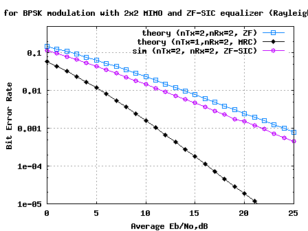
 for BPSK modulation")
